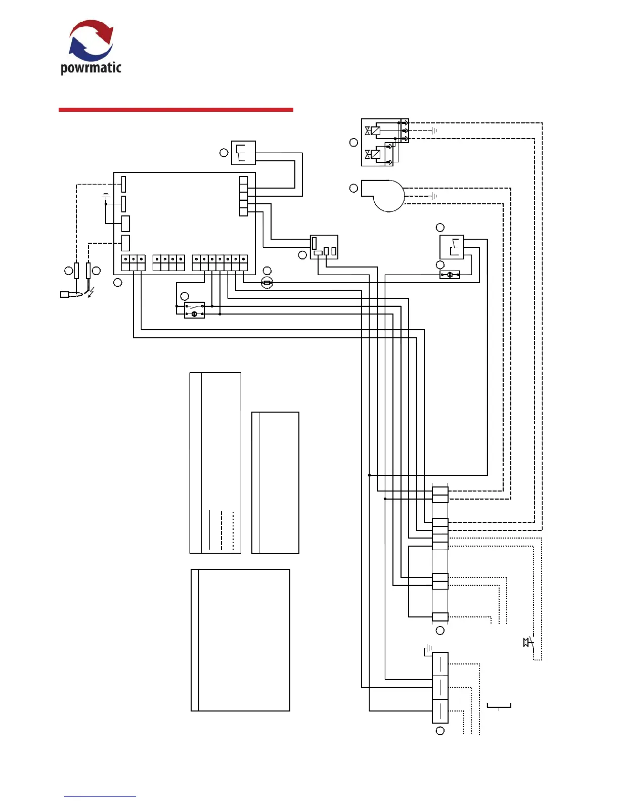
2.5 Wiring Diagrams
HEM Single Burner Unit (with ON/OFF Burner)
COM
NO
NC
L
LLL
E E
E
E
N N
N
N
1
1
5
5
6
6
11
11
12
12
15
15
16
16
C NO NC
23 1
LIVE
NEUTRAL
EARTH
B
r
0
.
5
Or 0.5
B
l
u
0
.
5
B
l
u
0
.
5
B
l
u
0
.
5
Yel 0.5
Wh 0.5
Br 0.5
B
r
0
.5
B
lu
0
.5
W
h
0
.
5
B
l
k
0
.
5
O
r
0
.5
B
lu
0
.
5
B
r
0
.5
B
r
0
.
5
Br 0.5
A
Yel 0.5
B
C
D
EF
G
H
I
B
lu
0
.
5
J K
L
M
COMPONENT LIST
Powrmatic part #
Model Specic
142403611
143100661
146522174
Model specic
Model specic
143000816
143000526
143070274
143100603
143100563
Model specic
142423003
Heat Demand 230V Input
Lockout 1 Indicator 230v Output
Lockout 1 Reset - Neutral Switch
A. Ignition Sequence Controller
B. GTLHR309 Limit Stat
C. Neon Indicator
D. Air Pressure Switch LGW3 A2
E. Main Gas Valve
F. Exhaust / Combustion Fan
G. 230v Relay
H. Fuse Holder 3.15A
I. Internal Lockout Reset Button
J. Hylec Terminal Block 3 Way
K. Terminal Block
L. Ignition Electrode
M. Rectication Probe
Br 0.5
Blu 0.5
Blu 0.5
Br 0.5
Blu 0.5
Br 0.5
Wiring Legend
NOTES
Connections made by Control board Assembler
Connections made by Final Assembler
Connections made by Installer
Br 0.5
Mains Input: 230v 50Hz 1ph Supply.
For input power refer to Installation instructions.
Warning: High voltages present at the ignition
electrode when the unit attemps to light.
External Controls
Connections
9
9
10
10
Main Fan Proving Pressure Switch
(Supplied by Others)
Blu 0.5
1
2
3
4
5
6
7
8
9
1
0
1
1
1
2
1
6
1
7
1
8
1
9
1
3
1
4
1
5
J
5
/ C
O
N
6
J
T
2
J
6
/
C
O
N
5
J
T
1
1
1
1
Gr/Yel 0.5
 Loading...