HEMNVx units should be serviced once per
year.
Gas Safety (Installation & Use) Regulations
(Current Issue)
It is law that all gas appliances are
installed, adjusted (converted if necessary)
and serviced by qualified persons* in accordance with
the current issue of the above regulations. Failure to
install appliances correctly can lead to prosecution.
It is in your own interests and that of safety to ensure
that the law is complied with.
* e.g. Gas Safe Registered
WARNING: Always switch o and disconnect
electricity supply and close the gas service
valve before carrying out any servicing
work or replacement of failed components.
The appliance manufacturer must be consulted
before replacing parts other than those
specied or recommended in the servicing
instructions.
Additional care must be taken if external units
are serviced in wet conditions. Consideration
must be given to additional requirements to
maintain a safe working environment e.g.
Weatherproof covers.
2.7.1. General
Full maintenance should be undertaken not less than
once per year by a qualied person. After any servicing
work has been complete, or any component replaced, the
air heater(s) must be fully commissioned and tested for
soundness as described in Section 2.2.
2.7.2. Main Burner Assembly Removal
1. Ensure that the gas service valve is turned OFF and then
unscrew the union nut situated immediately downstream
of it.
2. Remove the plug connection from the multifunctional
control.
3. Release the ange connections at the inlet and outlet of
the multifunctional control and remove the control.
4. Remove the spark and rectication probes from the side
of the burner noting which is which.
5. If required remove the burner manifold by removing the
four screws securing it to the burner assembly after having
rst removed the burner front cover.
6. Remove the four screws that secure the burner assembly
to the bulkhead and lift out burner assembly.
7. Using a sti brush, not a wire brush, brush the burners
to dislodge accumulated deposits. Inspect the burners
both internally and externally to ensure that they are clean.
Examine the injectors and if damaged or deteriorated,
replace with new ones of the correct size and marking. If
deemed necessary, clean the injectors. Do not broach out
with wire.
8. Inspect the heat exchanger tubes (See section 2.7.8)
9. Reassemble the injectors, manifold and burners in
reverse order to that above.
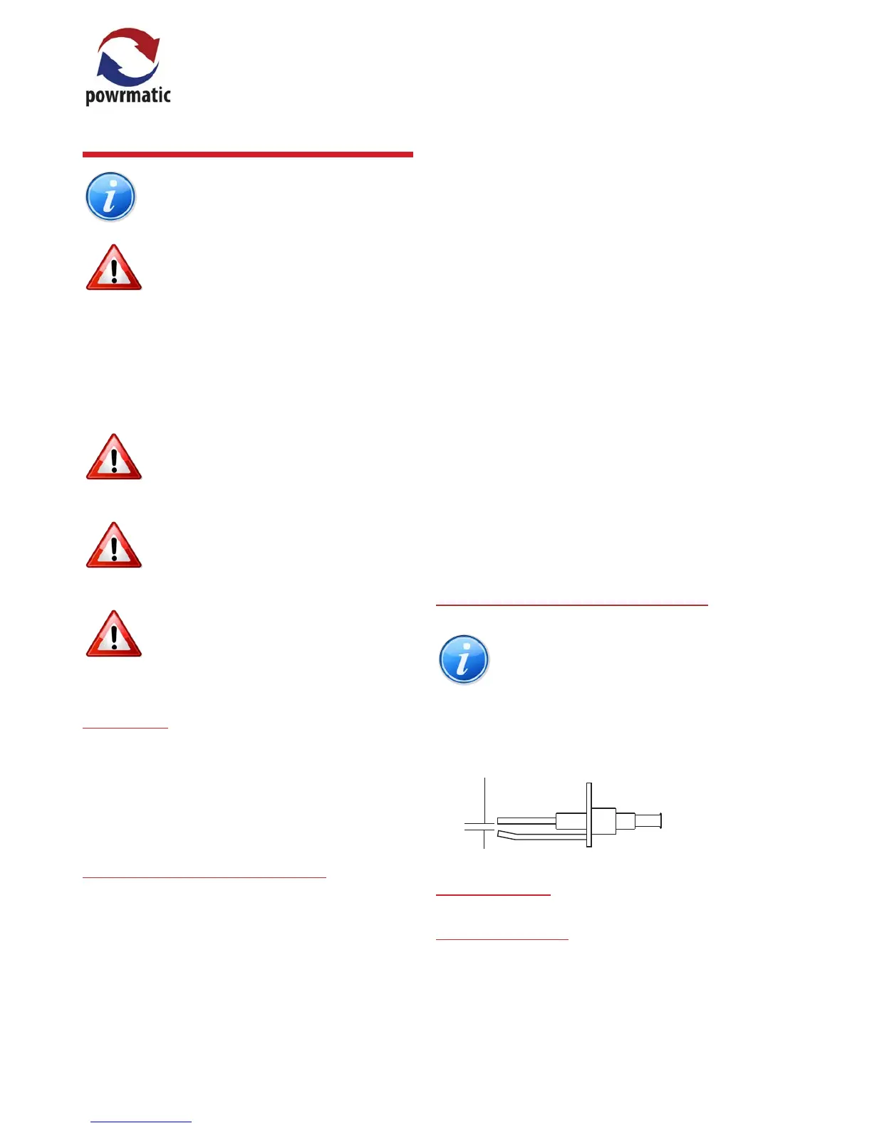
2.7.3. Ignition and Rectication Electrodes
Note: The ignition electrode is located at the
bottom of the burner assembly, the rectication
electrode is located at the top of the burner
assembly.
Inspect the electrodes, making sure that they are in a
sound and clean condition. In particular check that the
ignition electrode is clean and undamaged. Check that the
spark gap is 2.5mm and that the rectication probe is 10 -
12mm forward of the burner.
2.5mm
Ignition
Electrode Spark
Gap
2.7.4. Exhaust Fan
2.7.4.1. HEM 10 to 50
1. Disconnect the fan electrical connections from the main
terminal strip and the air pressure sensing tube from the
fan.
2. Loosen the six screws holding the main control panel,
lift the control panel up and clear of the xing position
(taking care not to snag the wiring) and move to one side.
2.7 Servicing
 Loading...