EasyManuals Logo

Powrmatic HEM-SL Series User Manual

Powrmatic HEM-SL Series
48 pages
To Next Page IconTo Next Page
To Previous Page IconTo Previous Page
Page #21 background imageLoading...
Page #21 background image
page no. 21 of 48
HEMNVx & HEMSL Range Users, Installation & Servicing Instructions Doc Ref M103 issue 3.1 Feb 2018.
Dual Burner Controls Compartment
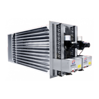
2.2 General Identication of Items
Exhaust
Header Box
Upper
Burner Set
Lower
Burner Set
Exhaust Fan
Exhaust Fan Flow
Sensing Point
Gas Valves
Gas Inlet
Controls
Panel
Upper Spark
Ignition Probe
Probe
Limit
Thermostat
Sequence
Controllers
Exhaust Fan
APS
Incoming
Electrical
Connection
Point
Limit
Indicators
Lockout
Indicators
Fuses
Burner Set
(behind Heat Shield)
Exhaust Fan Exhaust
Header Box
Spark Ignition
Probe
Gas Valv
Inlet
Control
Panel
Exhaust Fan
Flow Sensing
Point
Incoming Electrical
Connection Point
Sequence
Controller
Exhaust Fan
APS
Limit
Thermostat
Limit
Indicator
Lockout
Indicator
Fuse
e
Gas
Single Burner Controls Compartment
Single Burner Internal Components
Dual Burner Internal Components

Questions and Answers:

Question and Answer IconNeed help?

Do you have a question about the Powrmatic HEM-SL Series and is the answer not in the manual?

Powrmatic HEM-SL Series Specifications

General IconGeneral
BrandPowrmatic
ModelHEM-SL Series
CategoryControl Unit
LanguageEnglish

Related product manuals