P2%
P3%
Drop Out
Volts
5 10 20 30 40 50 60 70 80 90 100
Hold-in Voltage
0
0.3 0.5 1.0 2.0 3.0 4.0 5.0 6.0 7.0 8.0 9.0 10.0
10
1.0 1.5 2.0 3.0 4.0 5.0 6.0 7.0 8.0 9.0 10.0
20
2.0 2.5 3.0 4.0 5.0 6.0 7.0 8.0 9.0 10.0
30
3.0 3.5 4.0 5.0 6.0 7.0 8.0 9.0 10.0
40
4.0 4.5 5.0 6.0 7.0 8.0 9.0 10.0
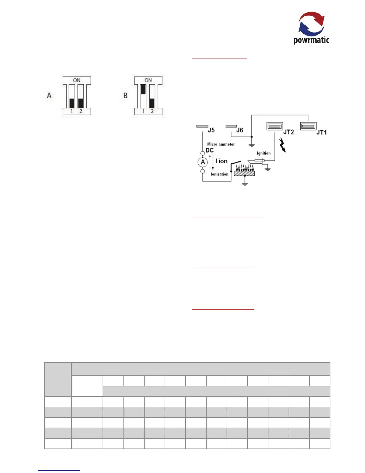
1. Slide switches 1 & 2 should both be to 'OFF' if one
modulating valve.is being driven (A), switch 1 'ON' and
swtich 2 'OFF' if two modulating valves are being driven (B)
2. Potentiometer P1 (Default setting 100%)
The control current of the V7335A is controlled by P1,
varying between 50% and 100% of the input signal.
E.g.
-When P1 is set at 100% (fully clockwise) maximum power
(165mA @ 22VDC) is provided to the modulation coil with a
10VDC input control signal.
-When P1 is set at 50% (fully anticlockwise) maximum
power (165mA @ 22VDC) is provided to the modulation coil
with a 5VDC input control signal.
3. Potentiometer P2
Controls the minimum drop-out voltage between 0% and
40% E.g.
- When P2 is set at 0% the drop-out voltage with an input
control signal of 0-10V-DC is 0.3V-DC.
- When P2 is set at 40% the drop-out voltage with an input
control signal of 0-10V-DC is 4.0V-DC.
4. Potentiometer P3 (Default setting 100%)
Controls the maximum hold-in voltage. Its proportional
value is added to the P2 setting E.g.
- When P2 is set at 0% and P3 is set at 5%, the hold-in
voltage of the burner relay is adjustable between 5% and
100% of the input control signal. If the input control signal
is set at 0-10V-DC the hold-in voltage of the relay is 0.5V-
DC.
- When P2 is set at 40% and P3 is set at 5%, the hold-in
voltage of the burner relay is adjustable between 45% and
100% of the input control signal. If the input control signal
is set at 0-10V-DC the hold-in voltage of the relay is 4.5V-
DC.
2.6.8. Flame Current
1. To measure the ame current connect a multimeter
capable of measuring micro amps as shown in the
following diagram.
2. Minimum current reading is 0.5mA and normal value
should be 1.5mA or higher.
Flame Current Measurement
2.6.9. Final Soundness Test
After making nal gas rate checks all joints on the gas
controls assembly must be tested for soundness using leak
detection uid.
2.6.8. Flame Safeguard
Whilst the burner is in operation close the gas service
valve. The burners should go to lockout within 1 second
2.6.9. User Instructions
The Users instruction supplied with the module are for the
end customer and must be supplied with the module.
The following table shows the relationship between P2 and
P3 settings.
 Loading...