5. Turn o the main burner, disconnect the pressure gauge
and replace the sealing screw. Turn on the main burner and
test for gas soundness around pressure test joint using a
leak detection uid. Replace access panel.
2.6.7.2. Modulating Regulator
1. Set external controls to ensure that the main burner is
o. Open the side access panel. Connect a pressure gauge
to the burner pressure test point on the multifunctional
control.
2. Set external controls so as to turn on the main burner
and maintain high re. Compare the measured burner
gas pressure to that stated on the data plate. In addition
it is advisable to check the gas rate using the gas meter
dial pointer ensuring that no other appliances supplied
through the meter are in operation.
3. Repeat 2 above with external controls set to maintain
low re.
4. If it is necessary to adjust either the high re or low re
pressures proceed as follows after removing the plastic
cover from the Modulating regulator.
‘O’ ring
Adjustment nut (9mm)
for minimum pressure setting
Adjustment nut (7mm)
for maximum pressure setting
Cap
Shaft
6.3mm AMP terminals
Note: Minimum re setting must be adjusted
rst after which the high re setting can be set.
Any adjustment of the minimum re setting
alters the maximum setting.
Minimum Setting
Disconnect electrical connection of modulating regulator
and turn burners back on and wait until the burner
pressure has stabilized. Turn 9mm adjustment nut for low
re pressure clockwise to increase and counter-clockwise
to decrease until the required pressure is obtained.
Reconnect modulating regulator and check high re
pressure, readjust if necessary.
Maximum Setting
Disconnect electrical connection of modulating regulator
and turn burners back on and wait until the burner
pressure has stabilized. Push shaft gently downwards to
the maximum adjustment screw and hold there. Turn 7mm
adjustment nut for high re pressure, clockwise to increase
and counter-clockwise to decrease, until the required
pressure is obtained. Release shaft. Repeat both settings if
necessary and then replace cover cap.
5. Turn o the main burner, disconnect the pressure gauge
and replace the sealing screw. Turn on the main burner and
test for gas soundness around pressure test joint using a
leak detection uid. Replace access panel.
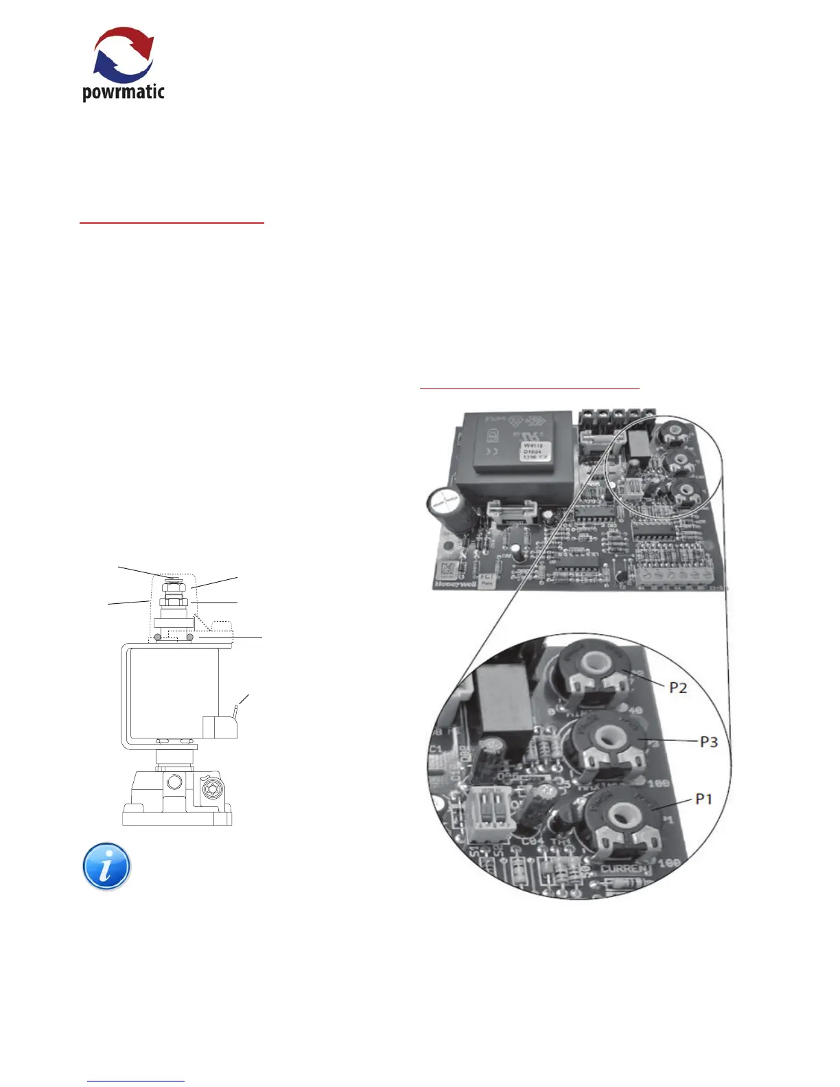
2.6.7.3. Modulating Interface Board
Modulating Interface Board
The MIB interfaces between a 0-10VDC control signal and
the modulating regulator. The following are applicable to
this application.
 Loading...