page no. 53 of 68
LX Range Users, Installation & Servicing Instructions Doc Ref M110 issue 1.0 Dec 2020.
2.6 Commissioning and Testing
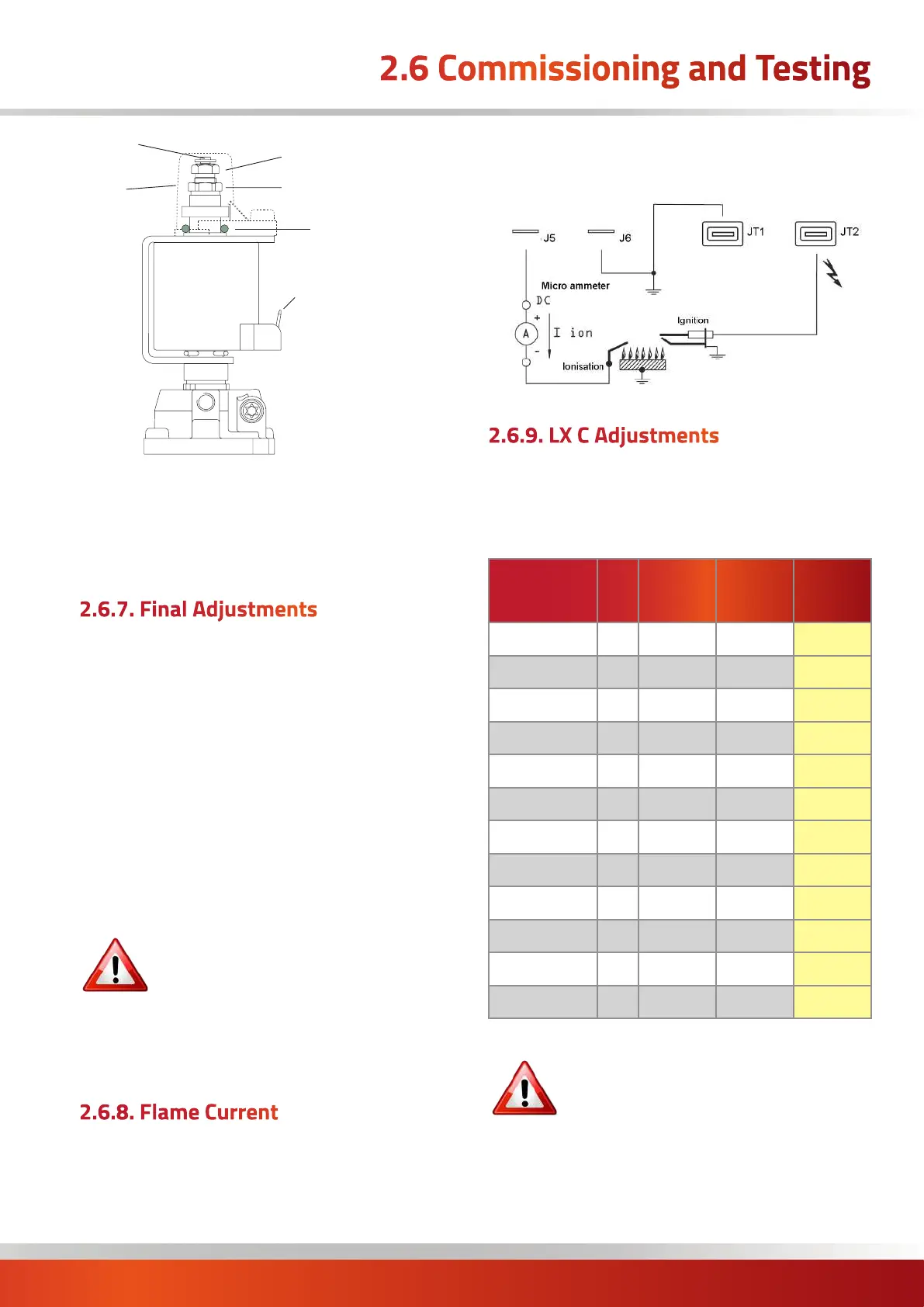
‘O’ ring
Adjustment nut (9mm)
for minimum pressure setting
Adjustment nut (7mm)
for maximum pressure setting
Cap
Shaft
6.3mm AMP terminals
5. Turn off the main burner,
6 Press and hold the ENGINEER TEST button for 2
seconds. Disconnect the manometer and tighten the
sealing screw in the gas valve.
2.6.7. Final Adjustments
1. After checking or setting the burner pressures, the flue
gas composition must be checked with a gas analyser by
sampling within the first section of flue fitted to the flue
outlet of the unit.
2. Remove the flue sample cover plug (if fitted) and insert
a calibrated gas analyser.
3. Operate the burner(s) and allow the flue gas
temperature to stabilise.
4. Take readings for both low and high fire. These figures
will also be required for the commissioning sheet.
The resulting CO/CO2 ratio must conform
to current directives and rules in force
for non-domestic gas fired heaters.
5. Test for gas tightness around pressure test joint using
a leak detection fluid e.g. soap solution. Replace access
panel.
2.6.8. Flame Current
1. To measure the flame current connect a multimeter
capable of measuring micro amps as shown in the
following diagram.
2. Minimum current reading is 0.5µA and normal value
should be 1.5µA or higher.
Flame Current
Measurement
2.6.9. LX C Adjustments
Using a clamp meter around the fan power cable and with
all side panels closed, check the running current of the
centrifugal fan once the heater is running and compared
with the table below. * currents shown for each fan
Model
Pha
Motor
kW
Typical
Running
Current
Max
Running
Current
LX15 1 0.55 2.0A 5.0A
LX20 1 1.1 3.1A 5.5A
LX25 1 1.1 4.2A 5.5A
LX30 1 1.6 4.3A 8.0A
LX35 1 1.6 4.7A 8.0A
LX40 1 1.6 5.8A 8.0A
LX50 1 2.0 7.6A 9.8A
LX60 1 2.2 10.0A 10.0A
LX70 1 2.2 11.0A 11.0A
LX90 1 2 x 1.6 6.4A* 8.0A*
LX120 1 2 x 2.2 8.5A* 10.0A*
LX140 1 2 x 2.2 10.0A* 10.0A*
WARNING: Exceeding the MAX running
current will cause the fan’s thermal overload
to trip!
Adjust the balancing dampers within the airflow ductwork
system to achieve a current suitable for the model in
question.
 Loading...