2.2.1 Electrical Connections
Warning: Wiring external to the MC200 must
be installed in accordance with I.E.E.
Regulations together with any local
regulations which may apply.
Wiring terminals are located beneath the electrical lower
front cover. Wiring should be completed in conduit, for
which knockouts are provided in the bottom of the casing.
Mains supply and control circuit wiring should be
completed in cables not less than 0.5mm² and fan circuit in
not less than 1.5mm².
The connection to the mains electrical supply can be taken
from the appliance or a separate ‘local’ supply, but in both
cases a local isolator must be tted adjacent to the MC200.
Should more than one appliance be controlled from one
MC200 an interfacing relay box MUST BE USED with the
MC200 driving the relay coils.
Warning: Sensor cable must be screened two
core and a minimum of 0.6mm² if solid and 7 x
0.2mm² if multistrand. The screen must be
grounded only at the MC200.
Wiring for the temperature sensor MUST BE RUN
SEPARATELY and apart from ALL other wiring. Failure
to regard this instruction may cause the MC200 to
malfunction and may render it faulty.
Under no circumstances must voltage be applied to the
sensor connections.
Warning: Burner Reset terminal is
internally connected to NEUTRAL when the
reset button is pressed.
2.2 Electrical Cable Installation
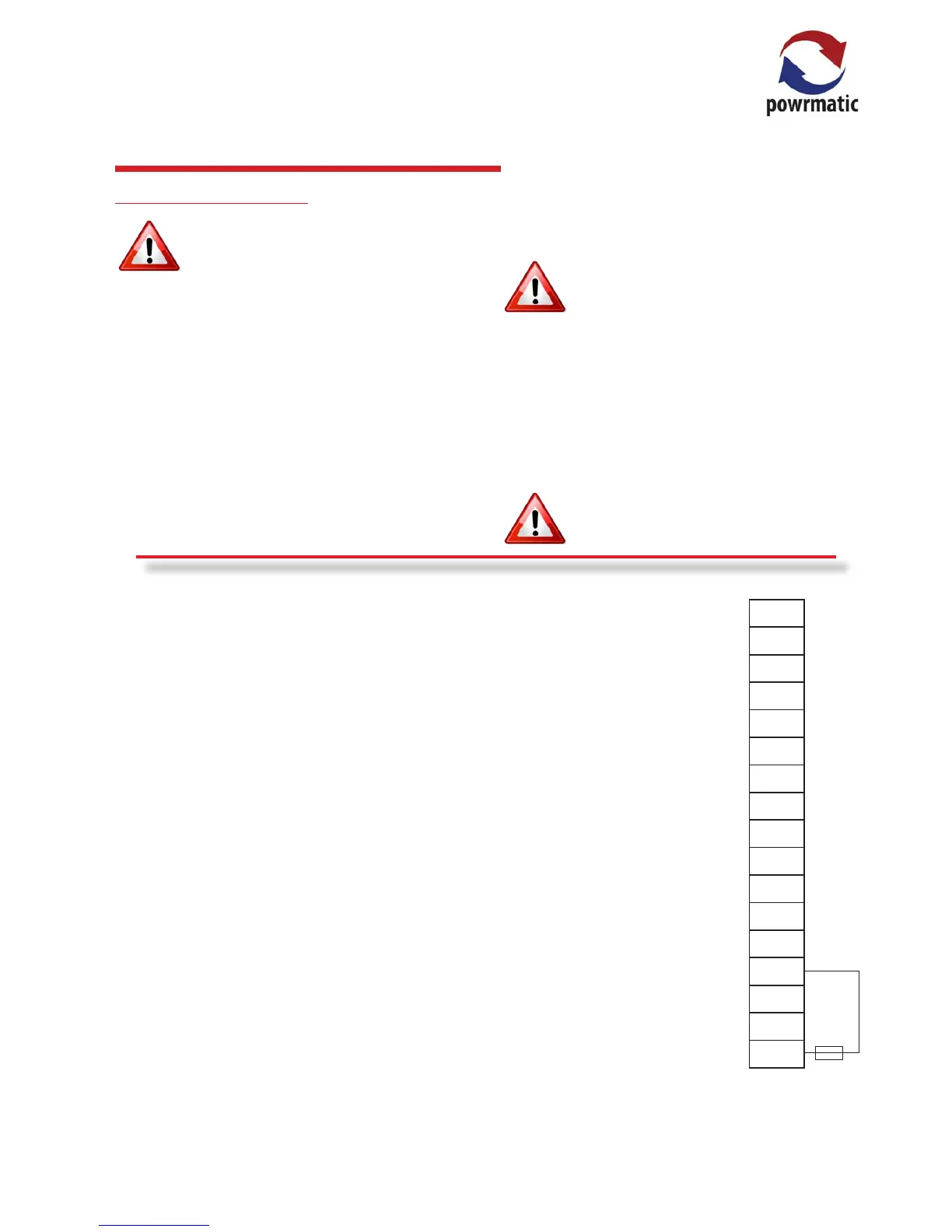
Terminal Type Function Terminals
SEN1 Input Connection for prime external sensor (not polarity sensitive)
COM Input Common connection for sensors and/or auxiliary switch
IN2 Input Connection for 2nd sensor (averaging) and or auxiliary switch
0-10V + Output 0-10Vdc output for modulation control MODULATION BURNERS ONLY
0-10V - Output 0Vdc (ground) output for modulation control MODULATION BURNERS ONLY
RESET Output NEUTRAL reset output (internally connected)
LOCKOUT Input Receives mains voltage lockout signal from burner
Heat Hi IN Input Hi Heat input (common relay contact)
Heat Hi OUT Output Hi Heat output (normally open relay contact)
Heat Lo IN Input Low heat/Heat input (common relay contact)
Heat Lo OUT Output Low heat/Heat output (normally open relay contact)
Fan IN Input Fan input (common relay contact)
Fan OUT Output Fan output (normally open relay contact)
L OUT Output 6.3A fused 230V output terminal for heat/fan circuits where required
N Input NEUTRAL
E Earth EARTH
L Input LIVE
Notes:
No Voltage - Voltage must not be applied to the sensor terminals. If a switch is tted accross COM and IN2, it must be volt free.
230V 50Hz Mains Voltage
Volt Free pair - If a voltage is required (230V, 24V, 110V etc) the appropriate voltage must be applied to the corresponding input
terminal.
 Loading...