1.2 General Requirements
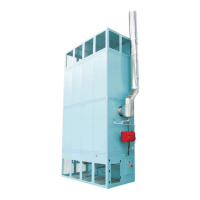
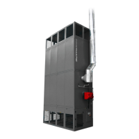
1.2.1 Gas Fired Heaters
1.2.1.1 Related Documents
The installation of the air heater(s) must be in accordance
with the rules in force and the relevant requirements of the
Gas Safety Regulations, Building Regulations and the
I.E.E. Regulations for Electrical Installations.
It should also be in accordance with any relevant require-
ments of the local gas region, local authority and fire
authority and the relevant recommendations of the follow-
ing documents.
Institution of Gas Engineers & Managers
IGE/UP/1 (Ed.2) Strength and tightness testing and purg-
ing of industrial and commercial gas installations.
IGE/UP/1A (Ed.2) Soundness testing and direct purging
of small low pressure industrial and commercial gas
installations.
IGE/UP/1B (Ed.2) Tightness testing and direct purging of
small Natural Gas installations.
IGE/UP/2 Gas installation pipework, boosters and com-
pressors on industrial and commercial premises.
IGE/UP/4 (Ed.2) Commissioning of gas fired plant on
industrial and commercial premises.
IGE/UP/10 (Ed.3) Installation gas appliances in industrial
and commercial premises.
British Standards & Codes of Practice
BS 9999 Code of practice for fire safety in the design,
management and use of buildings
BS 6230: 2011 Installation of Gas Fired Forced Convec-
tion Air Heaters for Commercial and Industrial Space
Heating.
1.2.1.2 Service Pipes
The local gas undertaking should be consulted at the
installation planning stage in order to establish the avail-
ability of an adequate supply of gas. An existing service
pipe must not be used without prior consultation with the
local gas undertaking.
1.2.1.3 Meters
A gas meter is connected to the service pipe by the local
gas undertaking or a local gas undertaking contractor. An
existing meter should be checked, preferably by the gas
undertaking, to ensure that the meter is adequate to deal
with the total rate of gas supply required.
1.2.1.4. Installation Pipes
Installation pipes should be fitted in accordance with
IM/16:1988. Pipework from the meter to the air heater
must be of adequate size. Do not use pipes of a smaller
size than the inlet gas connection of the heater. The com-
plete installation must be tested for soundness as
described in the above Code.
The complete installation must be tested for soundness as
described in BS 6230.
1.2.1.5. Boosted Supplies
Where it is necessary to employ a gas pressure booster
the controls must include a low pressure cut off switch at
the booster inlet. The local gas undertaking must be
consulted before a gas pressure booster is fitted.
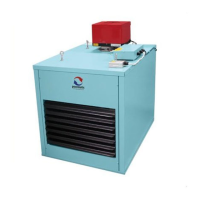
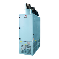
1.2.2 Oil Fired Heaters
1.2.2.1 Related Documents
The installation of the air heater(s) must be in accordance
with the rules in force and the relevant requirements of the
Building Regulations and the I.E.E. Regulations for Elec-
trical Installations.
It should also be in accordance with any relevant require-
ments of the local authority and fire authority and the
relevant recommendations of the following documents.
OFTEC Technical Book 3: Domestic & Commercial
requirements for oil storage and supply equipmement.
OFTEC Technical Book 4: Oil fired appliances & system
installation requirements.
OFTEC Easy Guides to non domestic oil feed pipes and
oil storage.
TE Powrmaster Heater Range Issue 4.0 March 2015 Page 7
qualified person.
5.2 Gas Installation
The whole of the gas installation, including the meter, should
be inspected and tested for soundness and purged in accordance
with the recommendations of the applicable IGE documents.
5.3 Fan Rotation
1. Whilst the main electrical supply is isolated and locked off
inspect the fan blades and ascertain the required direction of
rotation. See below.
1. Reinstate the electrical supply Turn the AUTO-OFF-MAN
switch to 'MAN'. Depending on the current state and setting of
the MC200 the mains fans may start immediately. If they do
not switch MC200 control (see MC200 manual supplied) to
‘Summer’ mode and then press the fan button on the front cover.
2. Ensure that the fan direction of rotation corresponds with the
direction of rotation arrow on the fan blades. If necessary turn
the AUTO-OFF-MAN switch to 'OFF', turn OFF the main
isolator and reverse the direction of rotation by interchanging
any two of the 3ph main supply leads at the terminal strip in the
electrical panel.
2. If appropriate reset the MC200 to Winter mode.