TE Powrmaster Heater Range Issue 4.0 March 2015 Page 9
2.1 Fitting the unit
2.1.1 General
Before installation, check that the local distribution
conditions, nature of gas and pressure (or oil type),
and adjustment of the appliance are compatible.
The air heater must be installed in accordance with the
rules in force and the relevant requirements of any fire
regulations or insurance company’s requirements apper-
taining to the area in which the heater is located, particu-
larly where special risks are involved such as areas where
petrol vehicles are housed, where cellulose spraying is
carried out, in wood working departments etc.
The following minimum clearances for installation and
servicing must be observed.
To the front 1.0m
To the rear The depth of the heater
To the side 1.0m
Above the heater 1.0m
Any combustible material adjacent to the air heater and
the flue system must be so placed or shielded as to
ensure that its temperature does not exceed 65 °C.
IMPORTANT:
No air heater shall be installed where there is a
foreseeable risk of flammable particles, gases
vapours or corrosion inducing gases or
vapours being drawn into either the heated air
stream or the air for combustion. In such cases
installation may only proceed if the air to be
heated and the air for combustion are ducted to
the heater from an uncontaminated source
preferably outside the building. In certain situa-
tions where only airborne particles are present
it may suffice to fit filters on the air inlet ducts of
the heater. Advice in these instances may be
obtained from Powrmatic Ltd.
2.1.2 Location
The location chosen for the air heater must permit:
- the provision of a satisfactory flue system and an
adequate air supply.
- adequate space for servicing and air circulation around
the air heater.
The heater(s) must not be installed in conditions for which
it is not specifically designed e.g. where the atmosphere
is corrosive or salty, and they are not suitable for outdoor
use unless the /EA style is specified. /EA heaters must be
installed on a plinth such that there is a minimum distance
of 0.5m between ground level and the lowest point of any
air inlet grilles.
Where the location of the air heater is such that it might
suffer external mechanical damage e.g. from overhead
cranes, fork lift trucks, it must be suitably protected.
TE heaters are for normal operation within an ambient
temperature range of -10 to 25°C.
2.1.3 Installation
TE heater installation may only be completed by Powr-
matic Ltd or their appointed representatives (unless previ-
ously agreed with Powrmaitc).
The heaters must be installed on a level noncombustible
floor capable of supporting the weight of the heater.
2.1.4 Combustion & Ventilation Air
Supply
There shall be provision for a supply of air for combustion.
In buildings having a design air change rate of less than
0.5 /h, and where TE heaters are to be installed in heated
spaces having a volume less than 4.7 m3 /kW of total
rated heat input grilles shall be provide at low level as
follows:-
The total minimum free area shall not be less than
270cm2 plus 2.25 cm2 per kilowatt in excess of 60 kW
rated heat input.
The air vent(s) should have negligible resistance and
must not be sited in any position where it is likely to be
easily blocked or flooded or in any position adjacent to an
extraction system which is carrying flammable vapour.
1) Installation in the heated space
In buildings with a design air change rate of 0.5 /h or
greater, additional natural or mechanical ventilation is not
necessary.
In buildings not having a design air change rate of 0.5 /h
the following apply.
Natural Ventilation
Grilles having a free area of at least 2cm² per kW of rated
heat input shall be provided at low level i.e. below the
level of the heater flue connection.
Mechanical Ventilation
Must ensure that the space air change rate is at least
0.5/h, must be of the ‘input’ type and interlocked to ensure
the heaters cannot work if the input system is not working.
2) Installation in plant rooms or enclosures
This type of installation is not applicable to TE heaters.
2.1.5. Gas Connection (if applicable)
A servicing valve and downstream union must be fitted at
the inlet to the air heater gas controls assembly to facili-
tate servicing.
The gas supply to the air heater must be completed in
solid pipework and be adequately supported.
Warning
When completing the final gas connection to
the heater do not place undue strain on the gas
pipework of the heater.
2.1.6. Oil Connection (if applicable)
Refer to the supplied burner installation instructions for
details regarding oil supply options.
2.1.7. Air Distribution System
Care should be taken to avoid impeding the air throw with
racking, partitions, plant or machinery etc.
A full and unobstructed return air path to the air heater(s)
must be provided.
Care must be taken to ensure that return-air intakes are
kept clear of sources of smells and fumes, and in special
circumstances where there is any possibility of pollution of
the air by dust, shavings etc., precautions must be taken
by carefully positioning return air intakes and by the provi-
sion of screens to prevent contamination.
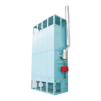
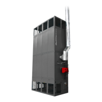
4.0.1 Mounting the fan module
Place the fan module on a level noncombustible floor
capable of supporting the weight of the heater. Fan
module should be fixed to the supporting structure
beneath by use of 4 x throughbolts or equivalent (not
supplied). This will prevent any movement brought about
by vibration whilst the heater is in operation.
4.0.2 Mounting the heat exchanger
module
The heat exchanger section should be aligned on top of
the fan section.
4.0.3 Connect the section
Use the section joining brackets to connect the separate
sections together.
The folded brackets should be fitted to connect the
corners; the flat brackets should be fitted to connect the
sides of the sections. Use the M8x25 bolts & washers
(supplied).
4.0.4 Mounting the extension module
(if required)
The extension section should be aligned on top of the
heat exchanger section and secured using section joining
brackets.
4.0.5 Mounting the air outlet module
The air outlet section should be aligned on top of the
extension section and secured using section joining
brackets.
4.0.6 Connect the flue
The flue tee should be secured to the heat exchanger flue
port by self cutting screws. Connect suitable pipework to
the condense drains from the flue tee and heat exchang-
er to drain off condense.
The flue stack will need to be supported using suitable
flue support brackets attached to an adequate supporting
structure provided by the building. Contact Powrmatic for
further details on the flue support bracket options avail-
able.
4.0.7 Connect the Burner
Burner cable plugs will need to be connected to the
burner cable sockets attached to the burner.
4.0.8 Connect up the electrics
Connect power supply cables and wire according to the
supplied wiring diagram. Other wiring (e.g. controls)
may be required and should only be wired according to
the supplied wiring diagram.
Fan/limit thermostat cables from the fan section will need
to be connected the terminal block in the black box on the
side of the heat exchanger section. Ensure all cable
colours are matched.
4.0.9 Check operation
Fully commission the heater and check for full operation.
NB. Control panel may differ from that shown, depending
on the choice of controls.
 Loading...