22
Zenex Plus User Manual
TEMPERATURE SENSOR INPUT
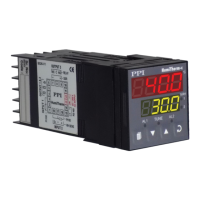
Connect Thermocouple or 3-wire RTD Pt100 sensor as shown below.
RTD Pt100, 3-wire
Connect single leaded end of RTD bulb to terminal T2 and the double leaded
ends to terminals T3 and T4 (interchangeable) as shown in Figure 6.3. Use
low resistance copper conductor leads of the same gauge and length. Avoid
joints in the cable.
Thermocouple
Connect Thermocouple Positive (+) to terminal T2 and Negative (-) to
terminal T3 as shown in Figure 6.3. Use correct type of extension lead wires
or compensating cable. Avoid joints in the cable.
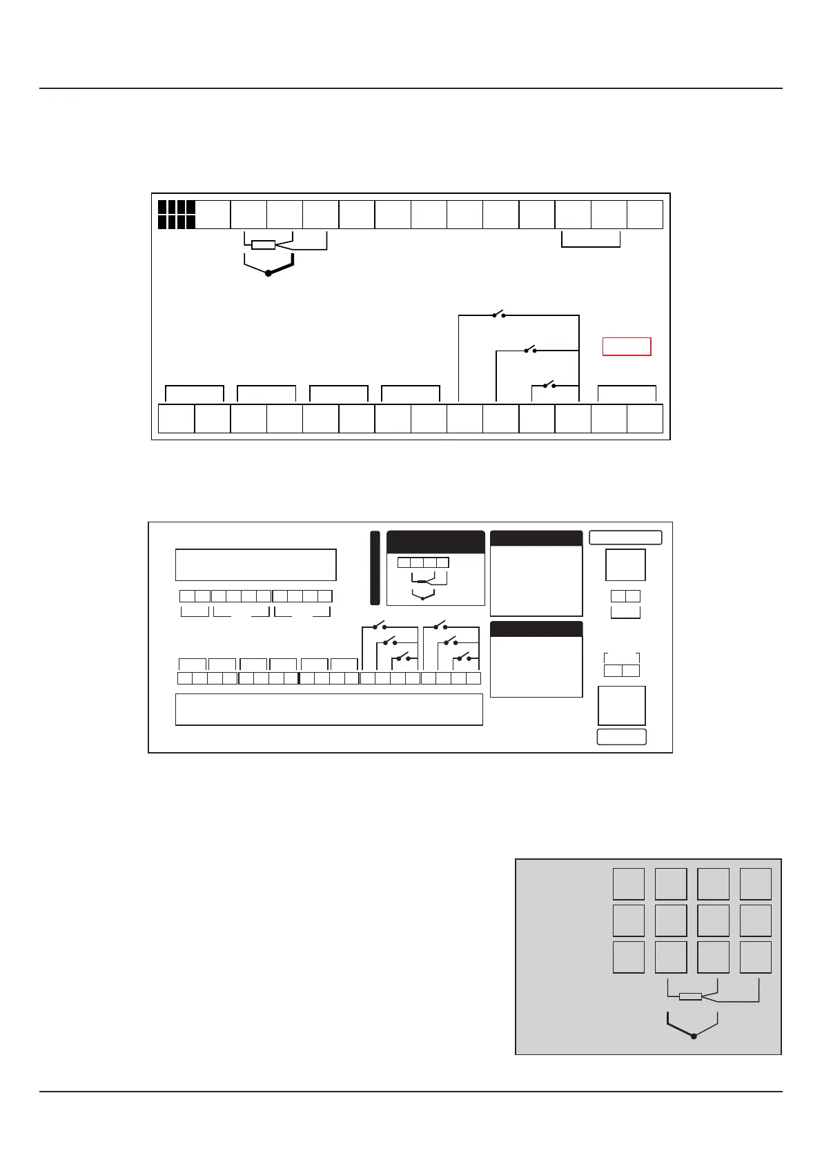
Figure 6.3
1 2
3
4
5
6
7
8 9 10
11 12
14
15
16 17
18
19 20 21
22 23
24
25
26 27
B+ B-
85 ~ 264
VAC
Supply
Pt100
TC
L
N
RS485
Serial
+
-
+
-
Heater
Control
Compressor
Control
Process
Alarm
Event
Alarm
+
- -
+ +
-
B124
Door Open
Timer Start
Alarm ACK
Zenex Plus
13
Pt100
26
27
28
+
-
25
TC
2
3
4
1
Old Version
New Version
T2
T3
T4
T1
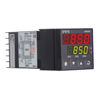
Figure 6.2(b) :
New Version
Figure 6.2(a) :
Old Version
24
23 3227
26
25 31302928
SUPPLY
33 34
85~265VAC
22
L N
21
9 106 7 85
17
18
19 20
14
15 16
13
RS485
B+ B-
2 3
4
1
+
-
+
-
+
-
DO-1 DO-2 DO-3
SERIAL COMM
+
-
DO-4
EXT.
VOLTAGE
+
-
AI-1 AI-2
AI-1 : Process Sensor
Connections
28
27
2625
Pt100
+
-
TC
+
-
DO-5
+
-
DO-6
11
12
DI-1
DI-2
DI-3
DI-4
DI-5
DI-6
Digital Output
DO-1 : Heater Control
DO-2 : Compressor
Control
DO-3 : Process Alarm
DO-4 : Event Alarm
DO-5 : Unused
DO-6 : Unused
Digital Input
DI-1 : Door Open
DI-2 : Timer Start
DI-3 : Alarm ACK
DI-4 : Unused
DI-5 : Unused
DI-6 : Unused
Zenex Plus B124-V2