9202QU01
LERBAKKEN 10, 8410 RØNDE DENMARK
Revision date:
2019-11-26
Version Revision
V1 R0
Prepared by:
PB
Page:
4/5
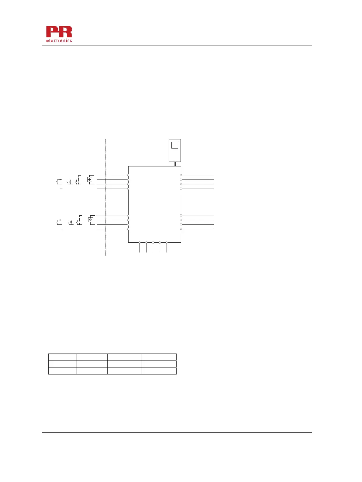
Ex input:
CH1 (terminal 41,42,43,44)
CH2 (terminal 51,52,53,54)
Uo: 10.6 VDC
Io: 12 mADC
Po: 32 mW
Lo/Ro: 1150µH/Ω
IIC or A,B IIB or C,E,F IIA or D,G
Ca or C
o.
2.0
F 6.0
F 18
F
La or L
o.
260 mH 780 mH 1000 mH
9202Bxx Installation:
-20 ≤ Ta ≤ 60ºC
44
43
42
41
54
53
52
51
34
33
32
31
14
13
12
11
9202
4501
91 92 93 94 95
Power
Rail
CH1
CH2
+
-
+
-
NAMUR Sensor
Switch
Switch w. Shunt
Contact Sensor
Supply terminal (31,32)
Voltage: 19.2 – 31.2 VDC
Status relay, terminal (33,34)
Class I Division 2 or
Zone 2 installation:
Voltage max: 32 Vac/ 32 Vdc
Current max: 0.5 Aac / 0.3Adc
(terminal 11,12,13,14)
(terminal 31,32,33,34)
(terminal 91,92,93,94,95)
U
m:
253 V max. 400 Hz
9202B1x
Terminal CH1(11,12) CH2(13,14)
Digital output: NPN output:
Voltage max. 30 VDC
Current max. 80 mA
9202B2x and 9202B3x
Relay output:
Terminal CH1(11,12) CH2(13,14)
Class I, Division 2
Zone 2 installation
Voltage max. 32 V AC / 30 VDC
Power max. 64 VA / 60 W
Current max. 2 AAC / 2 ADC
Hazardous Classified Location Unclassified Location or
Class I/II/III, Division 1, Group A,B,C,D,E,F,G Hazardous Classified Location
Zone 0,1, 2 Group IIC, IIB, IIA or Class I, Division 2, Group ABCD T4
Zone 20, 21
Class I Zone 2 Group IIC T4
9202 - Product version 9202-003 33