Do you have a question about the PR 5715 and is the answer not in the manual?
Covers critical safety warnings and the meaning of symbols used in the manual.
Provides essential safety guidelines, definitions, and environmental precautions for installation and operation.
Details UL installation requirements, calibration, operation, cleaning, and liability.
States the product's conformity with relevant directives and standards.
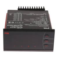
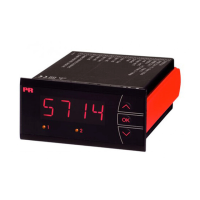
Illustrates the physical layout of the front and back panels of the indicator.
Describes the indicator's main features, intended uses, and functionalities.
Details the technical specifications like display type, input capabilities, and output options.
Provides guidance on how to mount and install the device, including protection ratings.
Covers specification ranges, supply voltage, consumption, and isolation voltage.
Details accuracy values and specifications for various input types like mA, Volt, Pt100, and TC.
Describes output capabilities, marine approval, GOST R approval, and authority requirements.
Explains how the device detects and reports sensor errors both inside and outside the valid range.
Illustrates how to connect various input, output, and supply signals to the device.
Provides a schematic overview of the internal components and signal flow of the indicator.
Details how to navigate menus and operate the device using the function keys, including setpoints.
Describes the two levels of password protection to secure access to menus and parameters.
Explains how to use the PReset PC program for configuring parameters and custom input types.
| Brand | PR |
|---|---|
| Model | 5715 |
| Category | Measuring Instruments |
| Language | English |