27
Replace the oil lling hole closing service
plug (red) positioned on the rear casing cover.
Checkthe correct quantity with the oil dipstick.
The oil dipstick must always be reachable, even
when the unit is assembled.
The pump shaft (PTO) must not be rigidly
connected to the drive unit.
The following types of transmission are
recommended:
- Hydraulics by ange, for proper application
consult with our Technical or Customer Service
Departments.
- V-belts.
- Universal joint (comply with the maximum
working angles recommended by the
manufacturer).
- Flexible coupling.
9.2 Rotation direction
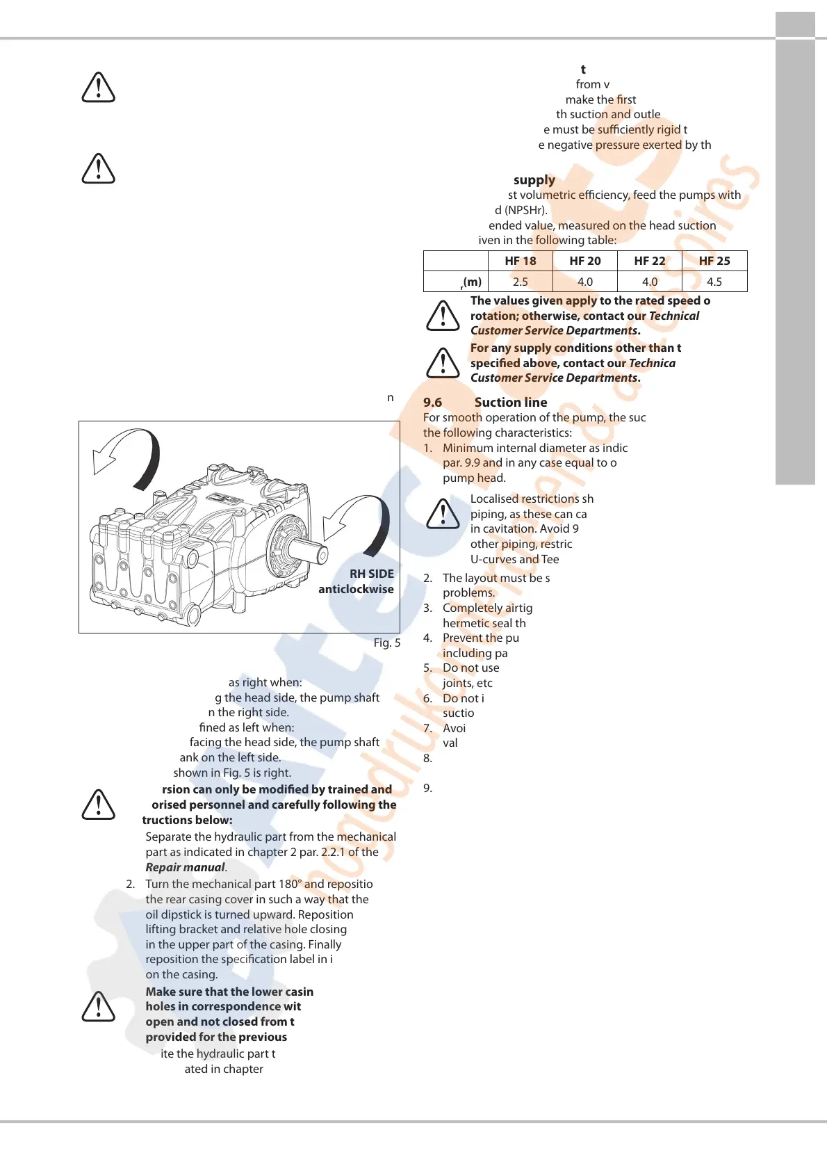
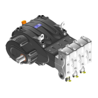
The rotation direction is indicated by an arrow located on the
casing near the drive shaft.
From a position facing the pump head, the rotation direction
will be as in Fig.5.
LH SIDE
clockwise
RH SIDE
anticlockwise
Fig.5
9.3 Version change
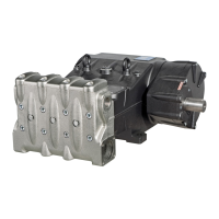
The pump version is dened as right when:
Observing the pump facing the head side, the pump shaft
must have a PTO shank on the right side.
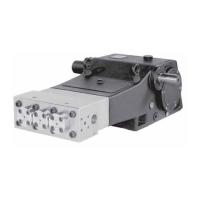
The pump version is dened as left when:
Observing the pump facing the head side, the pump shaft
must have a PTO shank on the left side.
Note. The version shown in Fig.5 is right.
The version can only be modied by trained and
authorised personnel and carefully following the
instructions below:
1. Separate the hydraulic part from the mechanical
part as indicated in chapter2 par.2.2.1 of the
Repair manual.
2. Turn the mechanical part 180° and reposition
the rear casing cover in such a way that the
oil dipstick is turned upward. Reposition the
lifting bracket and relative hole closing plugs
in the upper part of the casing. Finally, properly
reposition the specication label in its housing
on the casing.
Make sure that the lower casing draining
holes in correspondence with the pistons are
open and not closed from the plastic plugs
provided for the previous version.
3. Unite the hydraulic part to the mechanical part
as indicated in chapter2 par.2.2.5 of the Repair
manual.
9.4 Hydraulic connections
In order to isolate the system from vibrations produced by
the pump, it is advisable to make the rst section of the duct
adjacent to the pump (both suction and outlet) with exible
piping. The suction hose must be suciently rigid to prevent
deformation due to the negative pressure exerted by the
action of the pump.
9.5 Pump supply
To obtain the best volumetric eciency, feed the pumps with
a positive head (NPSHr).
The recommended value, measured on the head suction
ange, is given in the following table:
HF 18 HF 20 HF 22 HF 25
NPSH
r
(m) 2.5 4.0 4.0 4.5
The values given apply to the rated speed of
rotation; otherwise, contact our Technical or
Customer Service Departments.
For any supply conditions other than those
specied above, contact our Technical or
Customer Service Departments.
9.6 Suction line
For smooth operation of the pump, the suction line must have
the following characteristics:
1. Minimum internal diameter as indicated in the graph in
par.9.9 and in any case equal to or exceeding that of the
pump head.
Localised restrictions should be avoided along the
piping, as these can cause pressure drops resulting
in cavitation. Avoid 90° elbows, connections with
other piping, restrictions, reverse gradients, inverted
U-curves and Tee connections.
2. The layout must be such as to prevent cavitation
problems.
3. Completely airtight and constructed to ensure a perfectly
hermetic seal through time.
4. Prevent the pump from emptying when it is stopped,
including partial emptying.
5. Do not use 3 or 4-way hydraulic ttings, adapters, swivel
joints, etc. as they could jeopardise pump performance.
6. Do not install Venturi tubes or injectors for detergent
suction.
7. Avoid use of foot valves or other types of unidirectional
valves.
8. Do not recirculate the by-pass valve drain directly to the
suction line.
9. Provide for proper guards inside the tank to prevent that
water ow from the bypass and the tank supply line can
create vortexes or turbulence near the pump supply pipe
port.
10. Make sure the suction line is thoroughly clean inside
before connecting it to the pump.



 To Next Page