28
9.7 Filtration
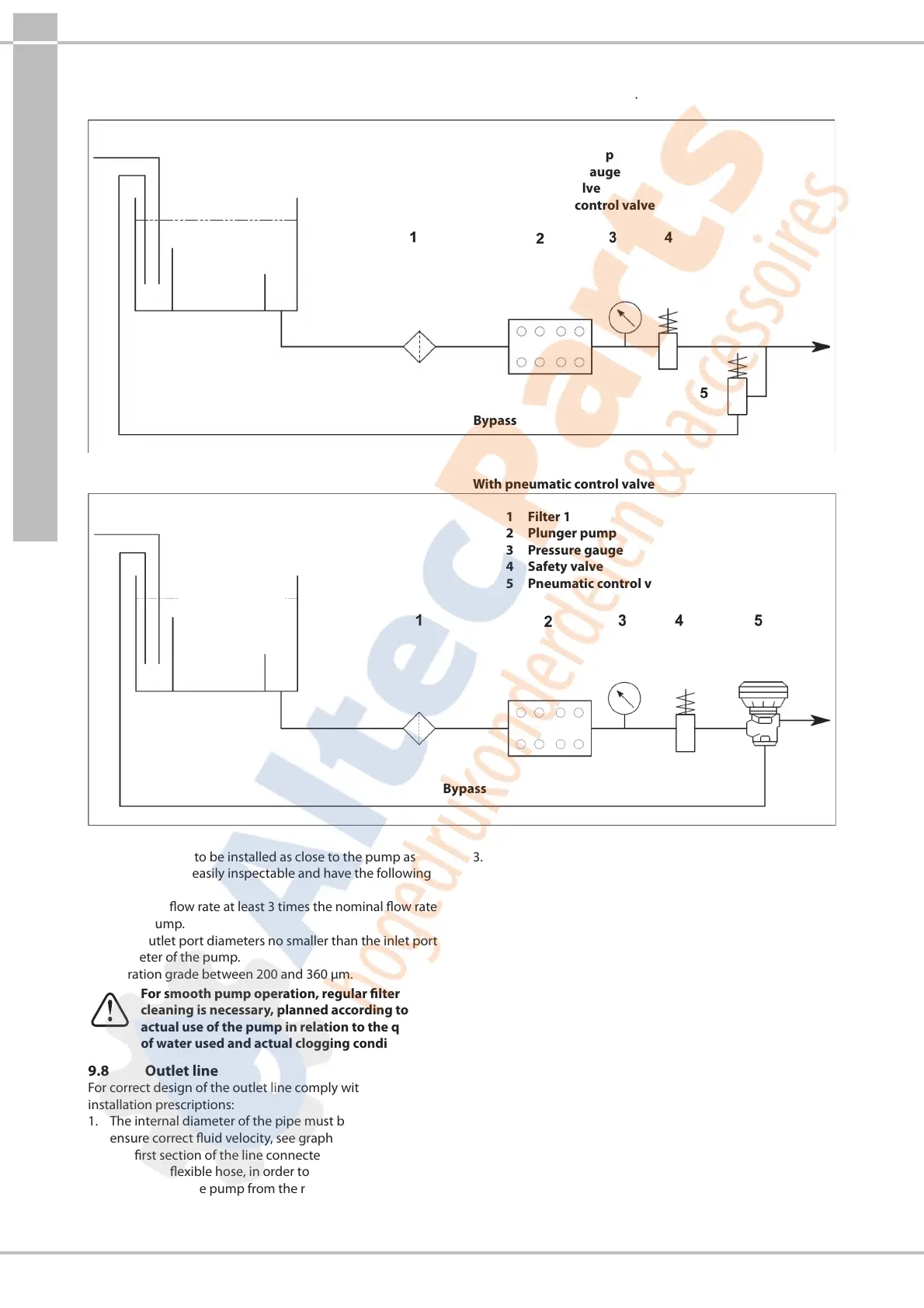
1 lter must be installed on the pump suction line, positioned as indicated in Fig.6 and Fig.6/a.
With a manually activated control valve
1 Filter 1
2 Plunger pump
3 Pressure gauge
4 Safety valve
5 Manual control valve
Inlet
Supply tank
Bypass
Fig.6
With pneumatic control valve
1 Filter 1
2 Plunger pump
3 Pressure gauge
4 Safety valve
5 Pneumatic control valve
Inlet
Supply tank
Bypass
Fig.6/a
The lter, which is to be installed as close to the pump as
possible, must be easily inspectable and have the following
specications:
1. Minimum ow rate at least 3 times the nominal ow rate
of the pump.
2. Inlet/outlet port diameters no smaller than the inlet port
diameter of the pump.
3. Filtration grade between 200 and 360 µm.
For smooth pump operation, regular lter
cleaning is necessary, planned according to the
actual use of the pump in relation to the quality
of water used and actual clogging conditions.
9.8 Outlet line
For correct design of the outlet line comply with the following
installation prescriptions:
1. The internal diameter of the pipe must be sucient to
ensure correct uid velocity, see graph in par.9.9.
2. The rst section of the line connected to the pump outlet
must be a exible hose, in order to isolate vibration
produced by the pump from the rest of the system.
3. Use high pressure pipes and ttings to ensure high safety
margins in all operating conditions.
4. The outlet line must always be provided with a
Max.pressure valve.
5. Use pressure gauges capable of withstanding the
pulsating loads typical of plunger pumps.
6. During the design stage, keep in mind the line pressure
drops that lead to a pressure reduction at the user with
respect to the pressure measured on the pump.
7. For those applications where pulses produced by the
pump on the outlet line may prove harmful or unwanted,
install a pulsation dampener of sucient size.
9.9 Calculation of the internal diameter of the
duct pipes
To determine the internal diameter of the duct, refer to the
following diagram:
Suction duct
With a ow rate of ~ 74 l/min and a water velocity of 0.5m/sec.
The graph line joining the two scales meets the central scale
showing the diameters, corresponding to a value of ~ 55mm.



 To Next Page