MW
52
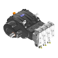
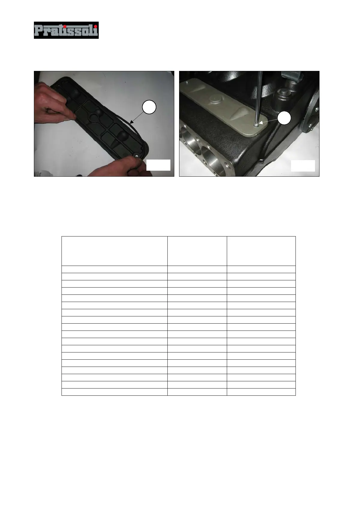
Insert the O-ring on the inspection covers (pos.c, fig.190) and assemble the covers with the use of 2+2
M6x14 screws (pos.c, fig.191).
Calibrate the screws with a torque wrench as indicated in paragraph 3 “Screw tightening calibration”.
3. SCREW TIGHTENING CALIBRATION
Screw tightening must only be performed with a torque wrench.
Description
Exploded
Drawing
Position
Tightening
Torque Nm
Casing cover M10x30 screw 89 H.P. – 91 L.P. 45
G1/2x13 casing plug 91 H.P. – 93 L.P. 40
Lifting bracket M16x30 screw 51 H.P. – 53 L.P. 200
Reduction gear cover M10x40 screw 81 H.P. – 83 L.P. 45
Ring gear stop M10x25 screw 76 H.P. – 78 L.P. 45
Reduction gear box M10x40 screw 81 H.P. – 83 L.P. 45
Upper and lower cover M6x14 screw 60 H.P. – 62 L.P. 10
Bearing cover M10x30 screw 89 H.P. – 91 L.P. 45
Con-rod fixing M10x1.5x80 screw 53 H.P. – 55 L.P. 65 *
Piston guide M10x35 screw 48 H.P. – 50 L.P. 60
Piston fixing M10x140 screw 30 H.P. – 18 L.P. 40
HP Valve cover M16x55 screw 26 333
LP Valve cover M16x45 screw 19 333
LP head G1/2" plug 4 40
G1/4”x13 head plug 14 H.P. – 21 L.P. 40
HP head M16x180 screw 28 333 **
HP head M16x150 screw 43 333 **
Valve opening device 2 40
* Achieve coupling torque tightening screws at the same time
** Tighten the screws starting cross-wise from the 4 inner screws, then continue with the 4 outer screws,
always tightening cross-wise.
fig. 190
1
fig. 191
1