13PM-727MV v6 2020-10 Copyright © 2020 Quality Machine Tools, LLC
Figure 3-9 Headstock tilted 45
o
counter clockwise
TRAMMING THE HEADSTOCK
As shipped, the mill is set to zero tilt, squared accurately
enough for initial “out of the box” test drillings, etc. For
more demanding project work thereafter, the spindle
needs to be set at precisely 90 degrees relative to the
table, in other words trammed. “Out of tram” may show
up as an oset of a few thousandths between entry and
exit of a deep hole, or as a scalloped eect when surfac-
ing a workpiece with a large-radius y cutter, exagger-
ated in Figure 3-10.
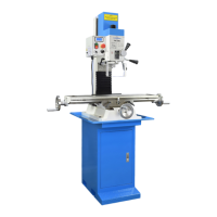
Figure 3-11 Sweep holder for dial indicator
The holder is a rectangular section aluminum bar with thread-
ed holes allowing the choice of two sweep diameters, 6” and
10”, measured from spindle centerline to indicator tip. The
smaller sweep can be used for front-to-back tramming, also
left-to-right as here. For more sensitive left-to-right tramming,
use the larger sweep.
Figure 3-10 Head tilt can aect surface atness
Tramming is the process of ne-tuning the headstock tilt
angle. Start by attaching a dial indicator to some form
of “sweepable” holder installed in the spindle, the aim
being to adjust tilt for the same reading on either side
of the X axis. The longer the radius arm, the greater the
sensitivity.
Figure 3-11 shows a typical shop-made holder; it has a
threaded arbor allowing the choice of two radius arms,
6 and 10 inches measured from spindle centerline to
indicator tip. A collet is used to hold the arbor, in this
example 5/8” diameter. The dimensions are arbitrary,
but note that the indicator must be rmly attached, and
the arm rock-solid relative to the indicator spring force
(which can be considerable on plunger-type indicators).
A suggested procedure for establishing tram:
1. Disconnect power.
2. Install the dial indicator.
3. Set the spindle drive to H-3 (this will allow the indi-
cator holder to sweep easily from side to side).
4. If the headstock has been tilted, reset it to the ap-
proximate zero degree position on the tilt scale, then
tighten the three nuts enough to avoid unexpected
headstock movement.
Tramming is done by ne-tuning the headstock tilt an-
gle. Tram is typically checked by attaching a dial indica-
tor to some form of “sweepable” holder installed in the
spindle, the aim being to adjust tilt for the same reading
on either side of the X axis. The longer the radius arm,
the greater the sensitivity.
– the paint seal may let go without warning. (First-time
tilting may also call for unusual eort on the wrench.)
Set the headstock to the desired angle by reference to
the tilt scale on the headstock base casting, then re-
tighten the nuts. The tilt scale was carefully installed in
manufacture, and is good to within ± 1 degree. A more
accurate means of angle measurement will be needed if
the project calls for greater precision.