Do you have a question about the Precision Power Power Class and is the answer not in the manual?
Details parameters like power bandwidth, THD, input topology, sensitivity, impedance, supply voltage, damping factor, and slew rate.
Lists output power (WRMS) for PC450, PC4100, and PC650 models at different impedances.
Instructions on not attempting to service the product yourself and contacting the dealer.
Advises caution regarding hearing loss due to extended use of high-powered audio systems.
Details the boost capabilities, frequency centers, Q-factor options, and remote control compatibility.
Defines crossover types (HP/LP), frequency ranges, and slopes for PC450, PC4100, and PC650 models.
Provides the length, height, and width for PC450, PC4100, and PC650 amplifiers.
Covers necessary tools, parts, fuse requirements, and general installation steps.
Provides a guide and chart to determine the correct wire gauge based on current draw and length.
Details critical safety steps before wiring, like battery disconnection and proper cable routing.
Explains how to properly ground the amplifier, including wire gauge and connection methods.
Details how to connect power, ground, and remote turn-on wires to the amplifier's PowerLock connector.
Explains connecting the remote turn-on lead and the function of the ACM-420 noise gate.
Guide for connecting speaker wires, noting polarity and gauge.
Explains how to bridge amplifier channels for a mono output and impedance considerations.
Describes how to run stereo speakers and a mono output simultaneously.
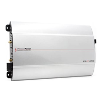
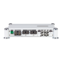
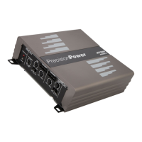
Illustrates and labels all connection points and controls on the PC450 amplifier.
Details the PowerLock connector for power and ground wire connection.
Explains the meaning of the green (on) and red (muting) indicator lights.
Describes the QBASS level control for boost adjustment.
Details the plug-in for the optional QBASS REMOTE™ dash mount control.
Explains how to adjust the rear crossover frequency.
Details where to plug in the rear RCA cables from the head unit.
Explains the use of the -12dB switch for high-level inputs.
Describes the function of the COMBINE switch to link rear to front inputs.
Explains how to adjust the front crossover frequency.
Details where to plug in the front RCA cables from the head unit.
Describes the RCA outputs providing summed mono low pass signal.
Used to match the output level of the head unit to the front channel.
Used to match the output level of the head unit to the rear channel.
Used to match the output level of the head unit to the sub channel.
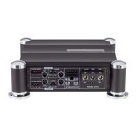
Details connecting speaker and remote wires via PowerLock connectors.
Connects rear channels to front inputs.
Selects Q-factor between 4 (boost narrow) and 2 (boost wide).
Adjusts the rear low pass crossover frequency from 44Hz to 315Hz.
Selects high pass or mono low pass signal for the rear speakers.
Adjusts the rear high pass crossover frequency from 20Hz to 5kHz.
Adjusts the front high pass crossover frequency from 20Hz to 5kHz.
Describes connecting RCA cables from the head unit to the amplifier inputs.
Details the QBASS circuit for up to 12dB boost centered at 40Hz.
Explains how this circuitry reduces noise for cleaner signal transmission.
Describes QBASS PLUS features, frequency selection, Q-factor, and level control.
Front HP and Rear HP/LP crossover adjustments and RCA outputs.
Front HP and Rear HP/LP/Summed Mono crossover capabilities.
Front and Rear HP crossover and fixed 90Hz subwoofer crossover.
Charts for setting crossover frequencies based on detent clicks.
Allows using front/rear outputs or combining front signal for rear channels.
Steps for setting amplifier gain to minimize noise and prevent overload.
Explains the heatsink design and the need for at least 2" clearance.
Details the thermally controlled fan in the PC4100 for heat management.
Guides users through common sound issues like no sound or sound in one channel.
Illustrates typical system configurations with PC450/PC4100 amplifiers.
Explains Short Circuit Protection and Thermal Protection modes.
Shows system with PC450/PC4100, ACM-420, and separate amps.
Illustrates PC4100 setup with different crossover settings.
Shows system with PC650, PAR-245 EQ, and DEQ-230 EQ.
Illustrates PC650 setup with two amps and bridged channels.
Internal signal flow and component relationships for the PC450 amplifier.
Internal signal flow and component relationships for the PC4100 amplifier.
| Brand | Precision Power |
|---|---|
| Model | Power Class |
| Category | Amplifier |
| Language | English |