Assembly Requirements
Precor recommends at least three people for this installation. DO NOT
attempt assembly by yourself.
When assembling the equipment, we recommend you:
• Follow the assembly instructions in order.
• Unpack the box(es) and assemble the equipment close to where you plan
to use it.
• Locate the equipment at least 40 inches (1 meter) away from walls or fur-
niture on either side of the equipment, and 40 inches (1 meter) away from
objects behind or in front of the equipment.
• Assemble the equipment on a solid, at surface so it remains level and
stable.
• Do not fully tighten fasteners until instructed to do so.
• DO NOT move equipment without assistance.
Hardware Kit
Discovery® Plate-Loaded Series
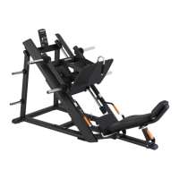
DPL601 Angled Leg Press | Assembly Guide
Dimensions W = 1448 mm/57.1 inches; H = 1429 mm/56.3 inches; L = 2436 mm/96 inches
Net Weight = 595 lbs/269.9 kg Max load weight = 1080 lbs/490 kg
DPL601 Angled Leg Press | Assembly Guide | P/N CW39174-113 B ENU | July 2022
©2022 Precor Incorporated | Discovery Plate-Loaded Series
1. Attach foot frames to cross frame
Attach the left and right foot frames to the cross frame using:
8 M12 x 35 mm socket head cap screws (SHCS)
8 13 mm at washers
NOTE Hand-tighten only.
2. Attach foot frames to rear frame
Attach the left and right foot frames to the rear frame using:
4 M12 x 35 mm SHCS
4 13 mm at washers
NOTE Hand-tighten only.
Required Tools
• Torque wrench with torque range to at least 150 ft-lb (206 N-m) and ts
the following hex bits: 6, 8, and 10 mm
• Socket wrench sets, metric and standard, plus extensions
• Open-end wrench sets, metric and standard
• Hex wrench sets, metric and standard, plus extensions
• Philips screwdriver
Foot frame, right
Foot frame, left
Cross frame
Rear frame
Main frame (240 lb/109 kg)
Carriage assembly
Back pad frame
Frame Components
Name Qty Name Qty Name Qty
Instructional placard 1 Weight storage bar 4 Set screw M8 4
Back pad 1 Weight storage bar bumper 4 M12 x 32 mm hex head screw 10
Seat pad 1 End cap 2 Flat washer 9 mm 11
Head pad 1 Hole plug 4 Flat washer 13 mm 34
Pivot shaft 1 M12 x 35 mm SHCS 24 Nylon lock nut M12 2
Weight horn 4 M12 x 175 mm SHCS 2 Cross recessed pan head screw 4
Weight horn end cover 4 M12 x 70 mm FHCS 1 M12 x 60 mm SCHS 6
Weight horn bumper 4 M8 x 15 mm BHCS 1
13
29
Frame Assembly
3. Attach main frame to rear and cross frames
WARNING The main frame weighs 240 lbs/109 kg. Ensure all three people have it
properly supported before assembly.
Attach the main frame to the rear frame and cross frame using:
10 M12 x 35 mm SHCS
10 13 mm at washers
NOTE Hand-tighten all frame hardware.
Add end caps and secure with:
4 Cross-recessed pan head screws
NOTE After attaching, remove the three protective labels on the left and
right foot frames and the cross frame.