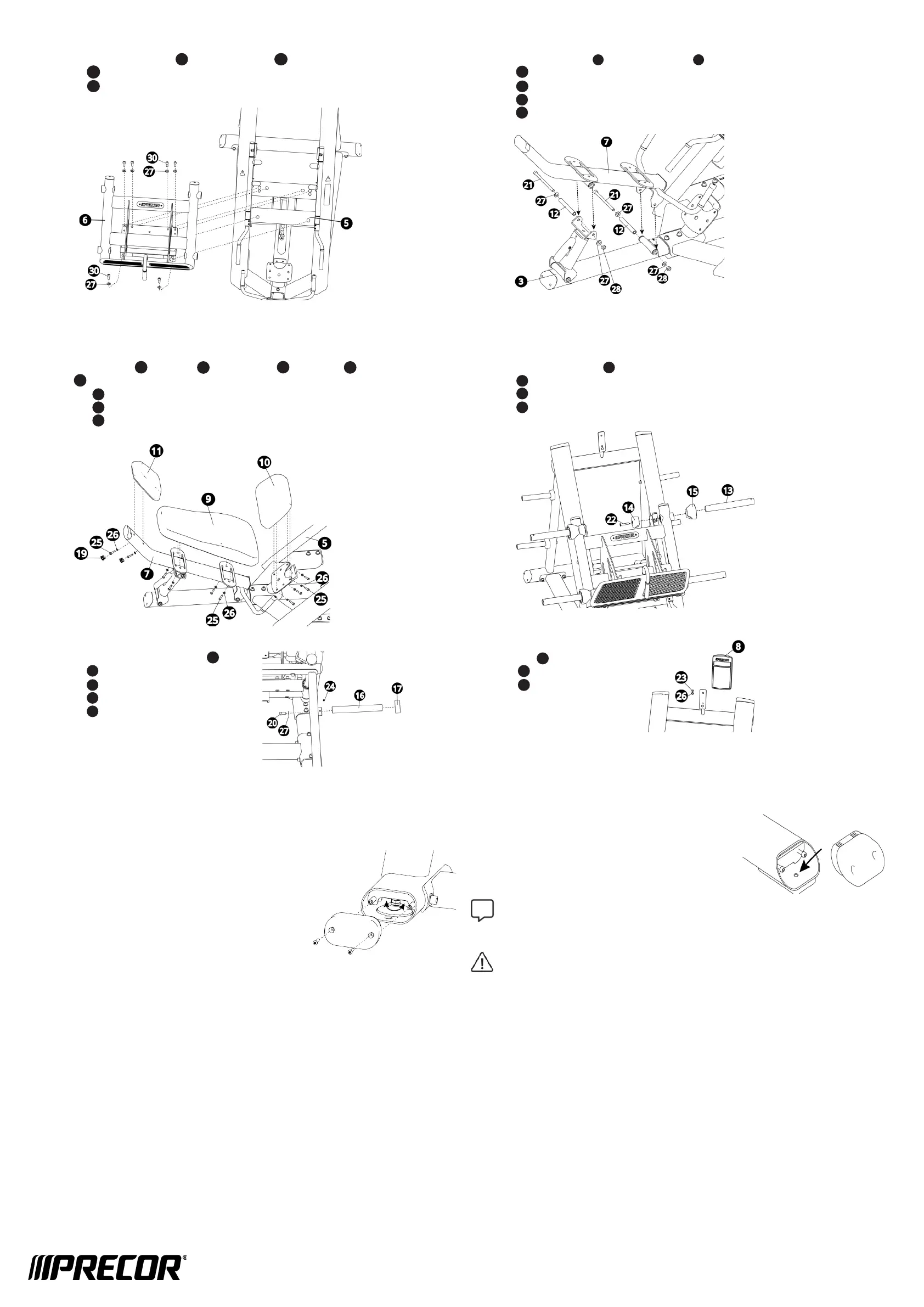
4. Attach carriage to main frame
Attach the carriage assembly to the main frame using:
6 M12 x 35 mm SHCS
6 13 mm at washers
IMPORTANT Tighten all M12 frame hardware to 90 N-m (63.38 ft-lb).
5. Attach back pad frame to cross frame
Attach the back pad frame to the cross frame using:
2 M12 x 175 mm SHCS
4 13 mm at washers
2 Pivot shafts
2 M12 nylon lock nuts
NOTE Tighten M12 fasteners to 90 N-m (63.38 ft-lb).
6. Attach pads to frames
Attach the head pad , back pad , and seat pad to the back and main
frames using:
10 M12 x 32 mm hex head screws
10 9 mm at washers
2 Hole plugs
NOTE Fully tighten.
Attach Pads, Horns, and Placard
8. Attach weight storage bars
Attach the four weight storage bars using:
4 set screws (fully tighten)
4 13 mm at washers
4 M12 x 32 mm SHCS
4 weight storage horn bumpers
NOTE Fully tighten.
9. Attach instructional placard
Attach placard using:
1 M8 x 15 mm BHCS
1 9 mm at washer
NOTE Fully tighten.
7. Attach weight horns to carriage
Attach the four weight horns to the carriage using:
4 weight horn bumpers
4 weight horn end covers
4 M12 x 70 mm FHCS
NOTE Fully tighten.
20
Bolt Equipment to Floor
Precor recommends that the strength equipment
be bolted down at all anchoring points. To bolt the
equipment to the oor, remove the end cap from the
frame base to expose the anchor point. Replace end
caps when bolting is complete.
NOTE As oor materials vary, it is important to
consult a licensed contractor to advise on proper bolting techniques and
appropriate fastener types.
CAUTION Standards can change. Precor recommends you keep apprised
of your local industry standards. Precor shall not be held liable for failure
to properly bolt the strength equipment to the oor.
Refer to your Discovery Plate Loaded Line owner’s manual for maintenance
information. For support, tutorials, and more information in additional
languages, visit us at www.precor.com.
Stabilize Equipment
After assembly, test the stability by pushing down on each corner of the unit. If the base
frame rocks or wobbles, adjust the feet to stabilize it.
1. Locate the round adjustable feet on the unit.
2. Remove the cover.
3. Use a 19 mm open-end wrench to turn the positioning
bolt. Turn right to move foot upward. Turn left to
move foot downward.
4. Continue to test the corners of the unit and readjust
feet as needed.
5. When the equipment is stable, re-tighten the jam nut
with an 18 mm open-end wrench to 50 ft-lb (67.79
N-m).
6. Replace the cover and tighten.
30
 Loading...