6
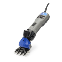
The Premier 4000s
High cutter speed under load, compact body
size and a powerful (high torque) motor are
specifi cally combined for high speed wool and
fi ber removal. This machine often "wows"
those used to other motor-in-the-handpiece
shearing machines.
This machine is designed for high speed
whole—fl ock shearing. When high speed wool
removal is important and practical, maximum
speed and power is preferred.
Premier Shearer
2009 Improvements
• Internal roller bearings instead of bushings (less heat, less wear and greater longevity)
• Sleek, low pro le head design.
• Suspended fork system (reduces risk of stripping the gear drive or breaking comb teeth)
• No cutter retainer or retaining spring (both caused hassles and broke too readily).
• Improved tensioning concept (spring clip is more effective at retaining than
cupped washers)
• No more black plastic sides (these were prone to falling off and frustrating users)
• Tension column far superior in design, less small/individual parts to wear out.
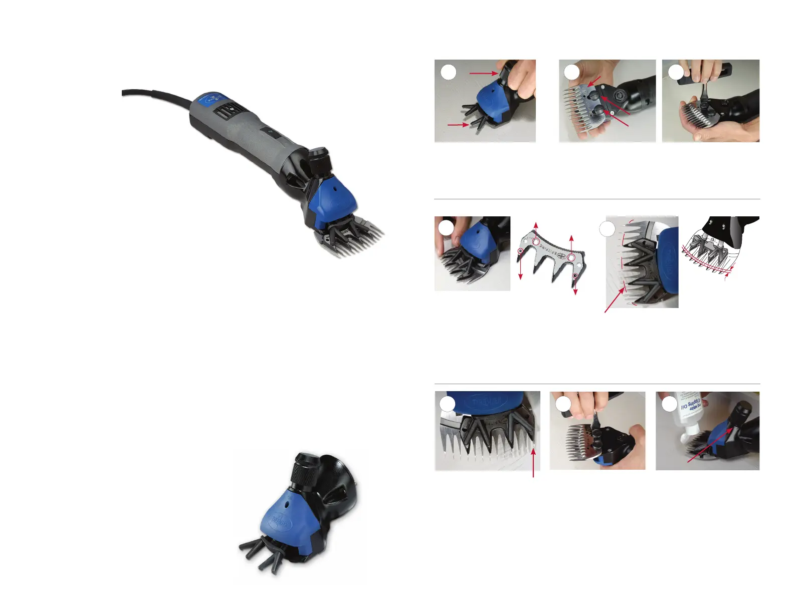
Interchangeable Shearing Head
Fitting Comb & Cutter to Unit (See next page)
• Shear sheep, llamas & alpacas
• Prepare cattle for sale
• Block show cattle and sheep
Changing your Shearing Head
On the old style models, the 4000c clipping head
takes different and longer screws than the 4000s
shearing head. When changing heads, you must
change screws also. Screws included with purchase of
each head. If you have the old style—the holes will be
non-counterboard (or sunk in). New ones are already
counterboard or sunk into the holes and screws are
the same in both head
7
Holes that the pegs
at the back of the
forks go into.
Holes the conical
points go into.
Tips to t comb & cutter to shear head
Setting correct
nal tension
Turn the machine back over
and tighten the tension knob
down until notable resistance
is felt. Then screw it a 1/2 turn
more. Apply shearing oil to
the comb and cutter. Start the
motor. Tweak tension according
to blade heat/cutting ability.
Getting Started
Loosen the tension knob (shown
above) so the two forks on the
shear head can move freely.
Turn machine over. Loosen
the 2 screws. Slide on the comb.
Premier logo on the comb in
this position.
Tighten both screws just
enough to hold the comb in
place. (You will securely tighten
the screws later.)
Cutter attachment
Turn machine back over. Insert the cutter under
the forks. Make sure that the 2 conical points of the
fork’s outer fi ngers are embedded into the holes on
the outer 2 teeth of the cutter (above). Then screw
the tension knob down against the cutter until light
resistance is felt.
Setting correct
cutter “throw”
When checking the cutter lead,
also make sure that the outside
cutter tooth covers no more than
1/2 of the outside tooth of the comb.
Adjust the comb left or right to
achieve this while also maintaining
the correct lead setting of 1/8".
Securing the
comb position
Tighten the comb screws
very fi rmly with a proper
screwdriver. This cannot be done
with an ordinary screwdriver.
Once the comb screws are
tight the cutters can be replaced
by releasing the tension knob.
The cutter should be
positioned 1/8" behind
the comb bevel.
Setting correct lead
Notice the cutter’s position in relationship to the
comb. The cutter should be positioned 1/8" behind
the comb bevel. If not, turn the machine over and
loosen the comb screws (as explained in step 1)
slightly. Adjust comb as needed—by sliding the
comb forwards or backwards.
Tension
Knob
Tension
Knob
Comb
Screws
Fork
Comb attachment
Logo
1.
2.
3.
4.
5.
6.
7.
8.
 Loading...