01
02
03
04
05
06
07
08
09
13
14
12
11
10
15
16
17
18
19
20
21
22
Oil
11
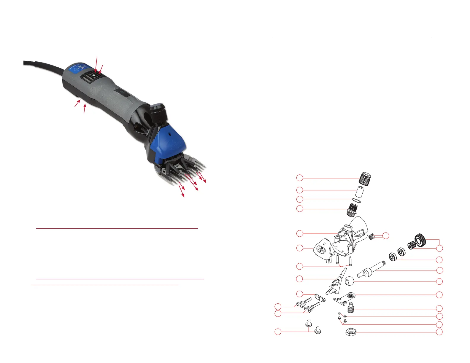
Item No. Part No. Description
01 82900401 1 - Tension nut
02 82900402 1 - Sliding sleeve
03 82900403 1 - Tension lock spring
04 82900404 1 - Lid bushing
05 82900405 1 - Shearing head (without accessories)
06 82900406 1 - Plastic head cover
07 82900407 1 - Head cover screw (2 required)
08 82900408 1 - Fork guide bracket
09 82900409 1 - Fork plate
10 82900410 1 - Fork fi nger (right)
11 82900411 1 - Fork fi nger (left)
12 82900412 1 - Comb screw
13 82900413 1 - Fulcrum lock nut
14 82900414 1 - Countersunk head screw
15 82900415 1 - Toothed washer
16 82900416 1 - Fulcrum post screw
17 82900417 1 - Tension spring plate
18 82900418 1 - Crank roller
19 82900419 1 - Crank spindle shaft
20 82900420 1 - Bearing
21 82900422 1 - Spindle hub with fi bergear
22 89600610 2 - Head screws and 2 washers (sold as a set)
4000s Shearing Head Parts
Premier recommends returning units
back to us for internal motor repairs.
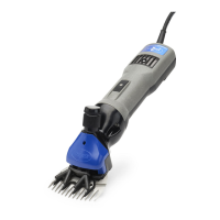
Outgoing Air
10
Important Warnings
Ventilated Motors:
Do not attempt to connect this motor to any Premier shear head or clipper head
acquired by yourself or your dealer before June 20, 2003.
If you do the motor will overheat and destroy the internal windings.
Why? The air from this motor is driven forward and out through the heads. This is a
new feature that results in cooler operating temperatures (up to 20 degrees less) of heads,
blades, combs and cutters. However, for this to occur the shear head or clipper head is
designed to enable the air to exit through the head. Older clipper heads can easily be
changed to allow this by knocking out the 2 black plastic kidney-shaped plugs on either
side of the drive shaft.
Shear heads supplied before June 20, 2003 will need to be sent back to
Premier for retro tting before they can be tted to this motor.
Shearing Machine Warning:
Do not switch this machine on unless the 4 point cutter is properly in place and
tensioned against the comb. As a guide, screw the tension knob down against the cutter
until resistance is felt, making sure that the fork fi ngers are tight against the cutter. Then
screw it another 1/2 turn further before switching the machine on.
Incoming
Air
Air Filter
Air Filter
Incoming Air