PREMIER E SERIES DUAL CAPACITY INSTALLATION AND MAINTENANCE MANUAL
23
4) If control responds improperly:
• Ensure that component being controlled is functioning (Compressor, Blower, Reversing
valve, etc.).
• Ensure that wiring from control to the component is functioning (use the diagnostic
outputs mode).
• If steps above check properly, replace unit control.
NOTE:
Refer to the wiring schematic on pages 14-15 for additional information.
REFRIGERANT SYSTEM
NOTE:
Verify that air and water flow rates are at proper levels before servicing the
refrigerant circuit.
To maintain sealed circuit integrity, do not install service gauges unless unit operation appears
abnormal (refer to the unit operating pressures and temperatures table below). If superheat and
subcooling are outside recommended ranges, an adjustment to the refrigerant charge may
be necessary.
OBTAINING PARTS
When contacting WFI for service or replacement parts, refer to the model number and serial
number of the unit as stamped on the serial plate attached to the unit. If replacement parts are
required, mention the date of installation of the unit and the date of failure, along with an explanation
of the malfunctions and a description of the replacement parts required.
IN-WARRANTY MATERIAL RETURN
Material may not be returned except by permission of authorized WFI warranty personnel. Contact
your local distributor or the WFI warranty department for warranty return authorization and assistance.
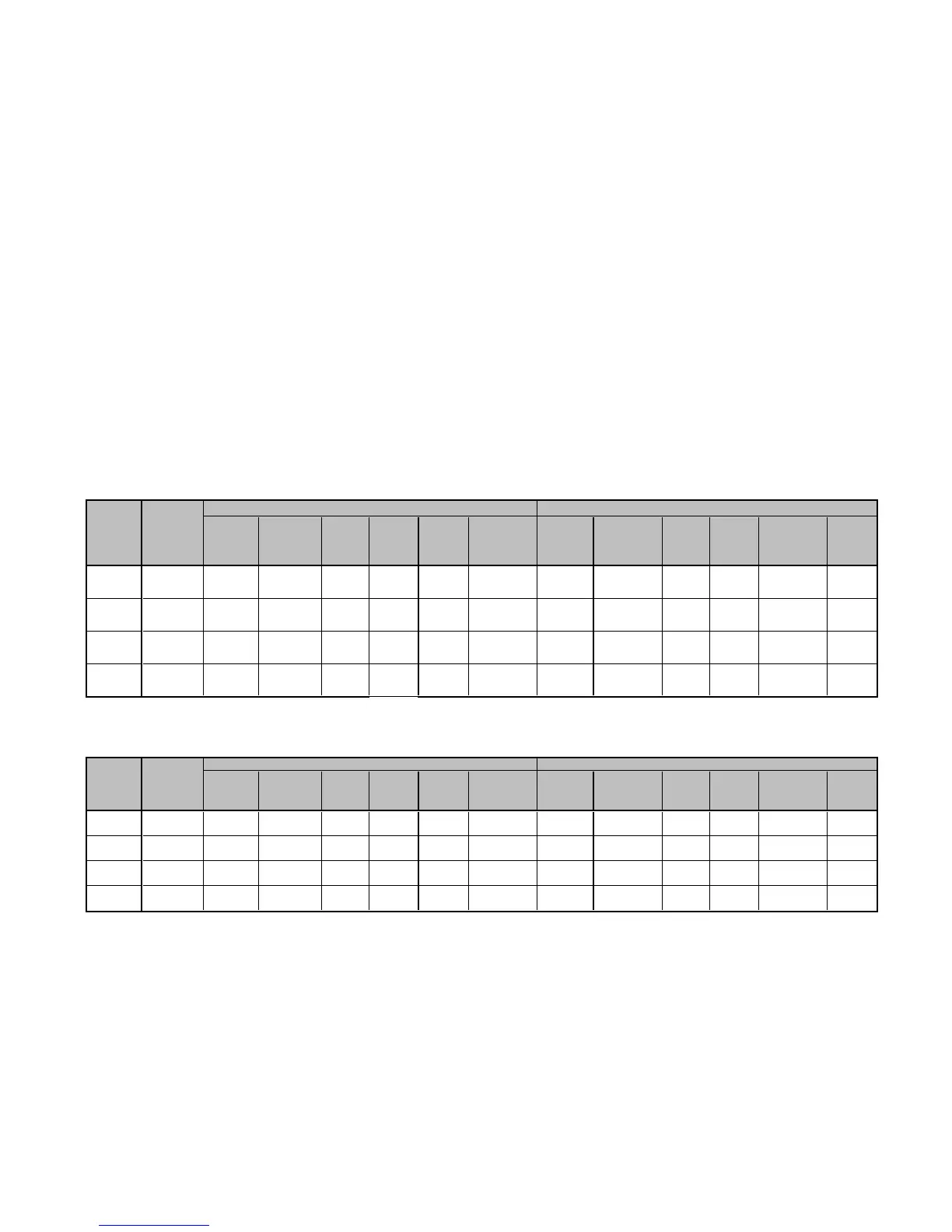
Unit Operating
Pressures*
Two cylinder operation
Cooling - No Desuperheater** Heating - No Desuperheater
Entering Water Suction Discharge Water Air Suction Discharge* Water Air
Water Flow Pressure Pressure Super- Sub- Temp Temp Pressure Pressure Super- Sub- Temp Temp
Temp °F GPM/TON PSIG PSIG heat cooling Rise °F Drop °F DB PSIG PSIG heat cooling Drop °F DB Rise °F
30 1.5 - - - - - - 64-72 285-320 11-16 13-19 5-7 15-21
3.0 - - - - - - 68-76 290-325 11-16 13-19 3-5 17-23
50 1.5 117-123 225-240 14-20 10-16 20-24 21-25 91-104 320-355 9-14 18-24 6-8 22-28
3.0 115-121 195-215 14-20 10-16 10-14 21-25 95-108 325-360 9-14 18-24 4-6 24-30
70 1.5 124-132 290-310 12-16 10-16 19-23 20-24 131-146 365-400 8-13 18-24 9-11 30-36
3.0 122-130 260-280 12-16 10-16 9-13 20-24 135-150 370-405 8-13 18-24 7-9 32-38
90 1.5 132-140 380-410 10-14 10-16 18-22 18-22 - - - - - -
3.0 130-138 350-380 10-14 10-16 8-12 18-22 - - - - - -
*Deduct 10# psig for E036
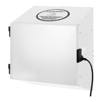
One cylinder operation
Cooling - No Desuperheater** Heating - No Desuperheater
Entering Water Suction Discharge Water Air Suction Discharge* Water Air
Water Flow Pressure Pressure Super- Sub- Temp Temp Pressure Pressure Super- Sub- Temp Temp
Temp °F GPM/TON PSIG PSIG heat cooling Rise °F Drop °F DB PSIG PSIG heat cooling Drop °F DB Rise °F
30 1.5 - - - - - - 76-84 269-282 8-12 2-8 4-6 12-16
3.0 - - - - - - 80-88 274-287 8-12 2-8 2-4 14-18
50 1.5 134-144 195-203 14-20 12-18 21-25 21-25 112-120 295-315 8-12 2-10 6-8 18-22
3.0 132-142 180-186 14-20 12-18 10-15 21-25 116-124 300-320 8-12 2-10 4-6 20-24
70 1.5 142-150 257-264 12-16 12-18 20-24 20-24 156-166 325-350 8-12 4-12 7-9 26-30
3.0 140-148 242-249 12-16 12-18 9-13 20-24 160-170 330-355 8-12 4-12 5-7 28-32
90 1.5 148-155 335-345 10-14 12-18 18-22 18-22 - - - - - -
3.0 146-153 320-330 10-14 12-18 8-12 18-22 - - - - - -
*Deduct 25# psig for E036
Replacement
Procedures