8
PREMIER E SERIES DUAL CAPACITY INSTALLATION AND MAINTENANCE MANUAL
OPEN LOOP SYSTEMS
NOTE:
For open loop/groundwater systems or systems that do not contain an antifreeze solution,
set SW2-Switch #2 to the “WELL” position,
(See schematic on pages 14 and 15).
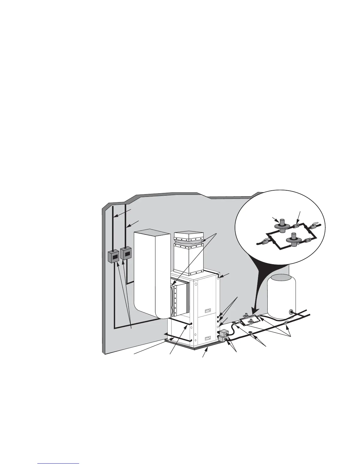
Typical open loop piping is shown in Figure 8. Always maintain water pressure in the heat
exchanger by placing water control valves at the outlet of the unit to prevent mineral precipitation.
Use a closed, bladder-type expansion tank to minimize mineral formation due to air exposure. Insure
proper water flow through the unit by checking pressure drop across the heat exchanger and
comparing it to the figures in Table 2 on page 21. Usually 1.5-2 gpm of flow per ton of cooling
capacity is recommended in open loop applications. In dual capacity units, stage 1 is half of the total
tonnage. Therefore, on a E048, the stage 1 solenoid should flow 3-6 gpm and stage 1 & 2 together
should flow 6-9 gpm.
Discharge water from the unit is not contaminated in any manner and can be disposed of in
various ways, depending on local building codes, i.e. recharge well, storm sewer, drain field, adjacent
stream or pond, etc. Most local codes forbid the use of sanitary sewer for disposal. Consult your
local building and zoning department to assure compliance in your area.
Open Loop
Groundwater
Systems
Figure 8 - Open System: Groundwater Application
Flexible
Duct Collar
Vibration
Absorbing Pad
P/T Plugs
Drain
Desuperheater
Connections
Auxiliary
Heater
Knockout
Low Voltage
to Thermostat
and Valve
Unit Supply
Auxiliary Heat Supply
Water Out
Water In
Shut Off
Valves
Boiler Drains
For HX Flushing
Solenoid Valve
(two should be used
in parallel.)
Flow
Regulator
Disconnects
(If Applicable)
Unit
Power