PREMIER E SERIES DUAL CAPACITY INSTALLATION AND MAINTENANCE MANUAL
3
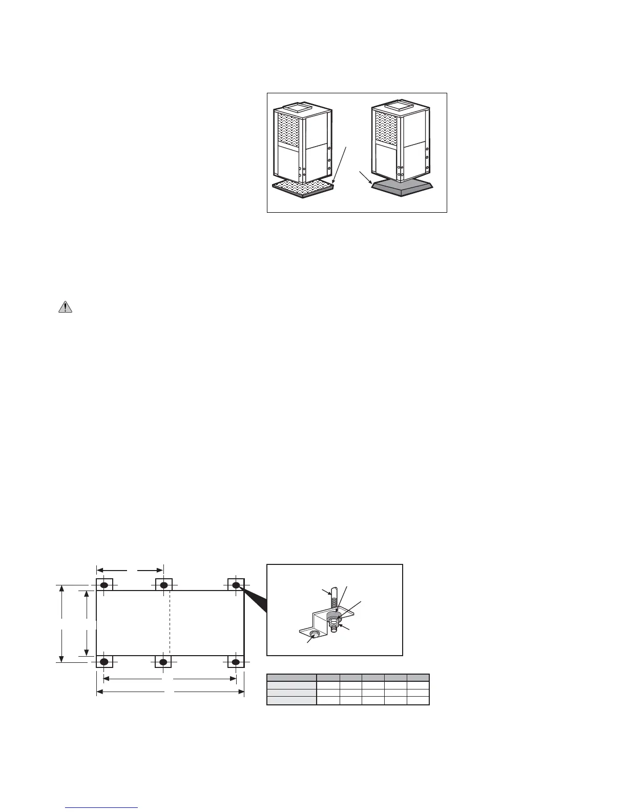
Vibration
Absorbing
Mesh
Air
Pad
Figure 1
– Vertical Unit Mounting
SETTING VERTICAL UNITS
Vertical units are available in left or right air
return configurations. Top flow vertical units should
be mounted level on a vibration absorbing pad
slightly larger than the base to provide isolation
between the unit and the floor. It is not necessary to
anchor the unit to the floor (see Figure 1). Bottom
flow units should be mounted level and sealed well
to floor to prevent air leakage.
NOTE:
If access to the left side of the unit will be limited after installation, remove the two mounting
screws on the left side of the control box before setting the unit (leave the two front mounting screws
intact). This will allow the control box to be removed with only the two front mounting screws for future
service.
SETTING HORIZONTAL UNITS
CAUTION:
Do not use rods smaller than 3/8” diameter since they may not be strong enough to
support the unit. The rods must be securely anchored to the ceiling.
Horizontal units are available with side or end discharge and may be field converted from one to
the other by replacing the discharge panel with a new panel which must be ordered separately.
Horizontal units are normally suspended from a ceiling by six 3/8” diameter threaded rods. The rods
are usually attached to the unit by hanger bracket kits furnished with each unit.
Lay out the threaded rods per the dimensions in Figure 2. Assemble the hangers to the unit as
shown. Securely tighten the brackets to the unit using the weld nuts located on the underside of
the bottom panel. When attaching the hanger rods to the bracket, a double nut is required since
vibration could loosen a single nut. The unit should be pitched approximately 1/4” towards the drain in
both directions to facilitate the removal of condensate. (see Figure 5A on page 6). Use only the bolts
provided in the kit. The use of longer bolts could damage internal parts.
Some residential applications require the installation of horizontal units on an attic floor. In this
case, the unit should be set in a full size secondary drain pan on top of a vibration absorbing mesh.
The secondary drain pan prevents possible condensate overflow or water leakage damage to the
ceiling. The secondary drain pan is usually placed on a plywood base isolated from the ceiling joists
by additional layers of vibration absorbing mesh.
Figure 2– Hanger Location and Assembly
C
B
D
E
Compressor
Section
Air Handler
Section
A
Vibration
Isolator
Washer
Hex Nuts
(not supplied)
Bolt and
Lockwasher
3/8”
Threaded Rod
(not supplied)
MODEL
CB
A
DE
E036, 048
E060
E072
27.8
27.8
27.8
29.9
29.9
29.9
70.5
75.5
80.5
72.0
77.0
82.0
25.5
25.5
25.5