29
Packaged and Split Rooftop Ventilator
© 2021 Mitsubishi Electric US, Inc.
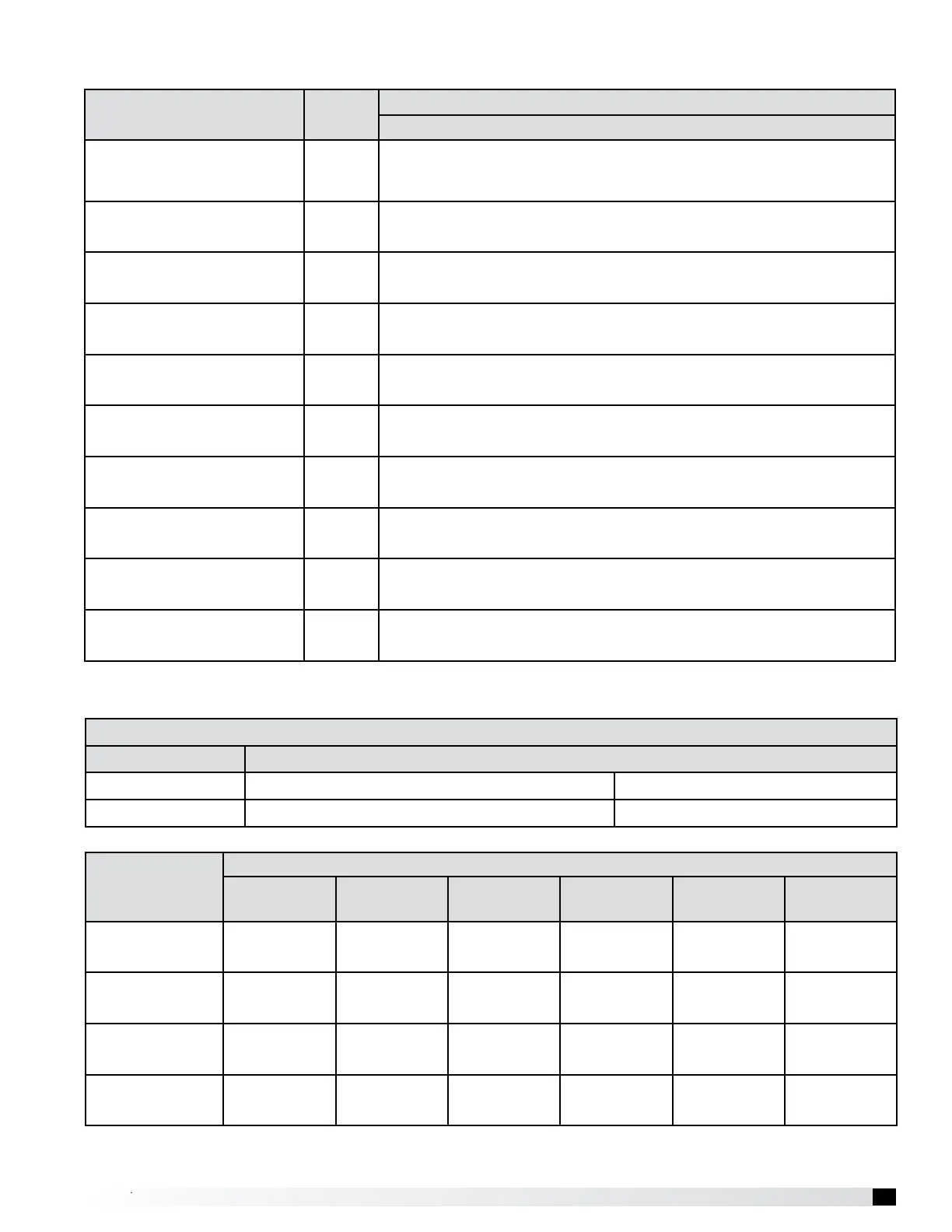
Parts Name Symbol
Model
MPF-1-**-**-96, 144, MPF-2-**-**-144, 192, 240
Liquid Pipe Thermistor TH22
Resistance 0ºC [32ºF]/15kΩ, 10ºC [50ºF]/9.7kΩ, 20ºC [68ºF]/6.4kΩ, 25ºC
[77ºF]/5.3kΩ, 30ºC [86ºF]/4.3kΩ, 40ºC [104ºF]/3.1kΩ
Gas Pipe Thermistor TH23
Resistance 0ºC [32ºF]/15kΩ, 10ºC [50ºF]/9.7kΩ, 20ºC [68ºF]/6.4kΩ, 25ºC
[77ºF]/5.3kΩ, 30ºC [86ºF]/4.3kΩ, 40ºC [104ºF]/3.1kΩ
Reheat Pipe Thermistor TH25
Resistance 0ºC [32ºF]/15kΩ, 10ºC [50ºF]/9.7kΩ, 20ºC [68ºF]/6.4kΩ, 25ºC
[77ºF]/5.3kΩ, 30ºC [86ºF]/4.3kΩ, 40ºC [104ºF]/3.1kΩ
Fuse (indoor controller board) FUSE 250V 6.3V
Solenoid Valve Coil SV10
208-230V Coil (208V 7W, 230V 8.5W) Normally closed port dimension
ø7.8
Solenoid Valve Coil SV11
208-230V Coil (208V 7W, 230V 8.5W) Normally closed port dimension
ø7.8
Linear Expansion Valve LEV3a
DC 12V Stepping motor drive port dimension ø6.4, 0~1400 pulse <at R410A
outdoor unit>
Linear Expansion Valve LEV3b
DC 12V Stepping motor drive port dimension ø6.4, 0~1400 pulse <at R410A
outdoor unit>
M-Net Terminal Block TB5 (M1, M2, S) 250V 20A
MODBUS Terminal Block TB485 (+, -, G) 250V 20A
Split DX Electrical Parts Specication-Refrigeration Control
Split DX Component Operation
Function of the LED’s on the Control Board
Symbol LED Operation Under Normal Conditions
LED 1 When M-NET power is applied LED ON
LED 2 M-NET communication signal LED ON
Component
DOAS Mode
Cooling Reheat Dehumidifying Fan Only Heating Off
SV10 Solenoid
Valve
Open Closed Open Open Open Open
SV11 Solenoid
Valve
Closed Open Closed Closed Closed Closed
LEV3a Linear
Expansion Valve
Modulating
1
Modulating
1
Modulating
1
Pulse = 41 Pulse = 41 Pulse = 41
LEV3b Linear
Expansion Valve
Modulating
1
Modulating
1
Modulating
1
Pulse = 41 Pulse = 41 Pulse = 41
1
Position will be determined by capacity requirements.