Do you have a question about the Prestige APS-520 and is the answer not in the manual?
Select mounting location inside passenger compartment, avoid steering interference.
Install LED in visible dash area for status indication and deterrent.
Route antenna above belt line for best reception, considering windshield shielding.
Mount switch in accessible location, preferably lower dash, for programming.
Secure siren in engine compartment away from hot/moving parts, pointed downward.
Mount switch to grounded metal surface for hood security and remote start safety.
Locate relay near ignition switch and secure to harness or metal brace.
Select a centrally located, solid surface for consistent sensor operation.
Connect Red/White and Red Fused wires to constant 12 VDC battery source.
Connect Yellow to ignition source, White to parking light, Orange to starter inhibit relay.
Connect White/Black to siren, Brown to negative door trigger.
Connect Purple to positive door trigger, Dark Green to instant trigger input.
Connect Black to chassis ground, Dark Blue to pulsed channel 3 output.
Connect Green/Black for channel 4 output, Black/White for horn output.
Connect Green/White for entry illumination, shock sensor harness to module.
Connect LED, Antenna/Transceiver, and Valet/Program switch to control module.
Wire the 2-pin harness for door lock/unlock circuits based on vehicle wiring.
Diagrams for 5-wire polarity reversal, adding actuators, and negative door locks.
Procedure for setting transmitter channels and programming features.
Learn vehicle's dome light delay to prevent false zone triggers.
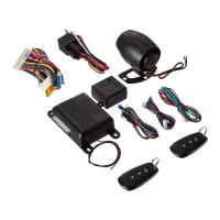
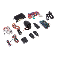
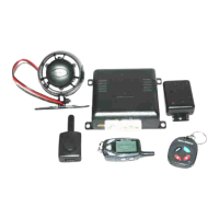
Secure module, harness, check vehicle systems, replace panels, and test.
| Brand | Prestige |
|---|---|
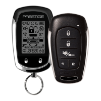
| Model | APS-520 |
| Category | Car Alarm |
| Remote Start | Yes |
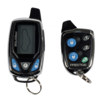
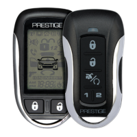
| Remote Control | Yes |
| Keyless Entry | Yes |
| Shock Sensor | Yes |
| Panic Mode | Yes |
| Starter Kill | Yes |
| Valet Mode | Yes |
| Operating Voltage | 12V |
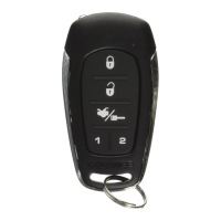
| Number of Buttons on Remotes | 4 |
| Number of Remotes Included | 2 |
| Two-Way Communication | No |
| Range | Up to 1500 feet |