CAVA - MANUAL
3 | CAVA – Manual | AntecControls.com
MECHANICAL INSTALLATION
It is recommended to mount Cava™ at approximately 5½’ to 6’ from the floor. This will allow the interface to be at an
appropriate height for use during setup and during normal operation.
Mounting Options
Cava™ can be mounted in one of three ways. Option A uses a pre-cut single gang junction box cut-out. Option B uses an on-
site created cut-out using a Jigsaw. Option C uses an on-site created circular cut-out.
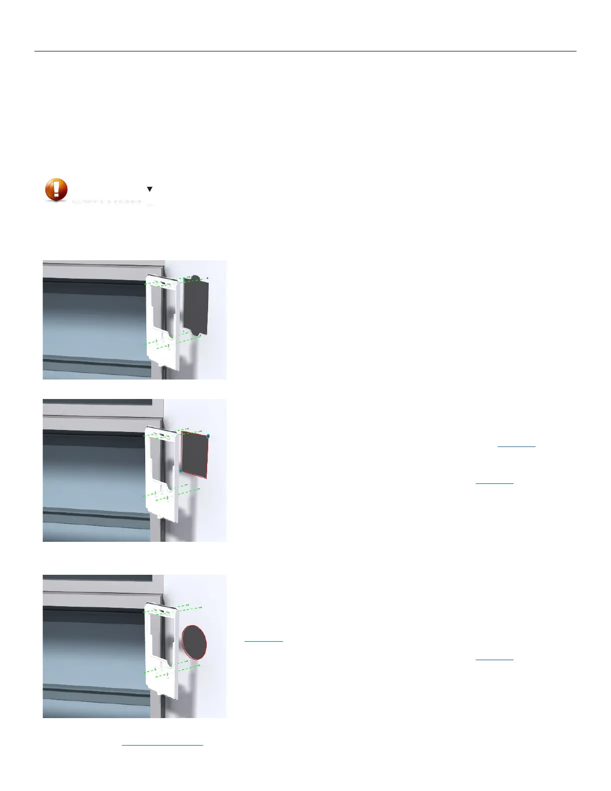
Option A
Mount Cava™ using a pre-cut single gang junction box cut-out.
Mount the backplate to the fume hood using four #6 self-tapping metal screws (minimum 3/8”
STEP 2
Attach Cava™ and tighten the set screw once electrical installation is complete.
Option B
Mount Cava™ using a Jigsaw cut-out.
STEP 1
Mark the appropriate mounting location for Cava™.
STEP 2
Drill two 1/4” to 1/2” pilot holes at either corner of the provided template in Appendix A.
STEP 3
Using a jigsaw, cut four lines to cut-out a square.
STEP 4
Drill four 7/64” mounting holes according to the provided template in Appendix A.
Deburr and file any sharp edges if they are present to prevent any edges from cutting the
Mount the backplate to the fume hood using four #6 self-tapping metal screws (minimum 3/8”
STEP 7
Attach Cava™ and tighten the set screw once electrical installation is complete.
Option C
Mount Cava™ using a circular cut-out. This is the least preferable mounting option, as the
hole provides the least access to the wiring terminals.
STEP 1
Mark the appropriate mounting location for Cava™.
Drill a 2.25” hole in the front panel of the fume hood according to the provided template in
STEP 3
Drill four 7/64” mounting holes according to the provided template in Appendix A.
Deburr and file any sharp edges if they are present to prevent any edges from cutting the
Mount the backplate to the fume hood using four #6 self-tapping metal screws (minimum 3/8”
STEP 6
Attach Cava™ and tighten the set screw once electrical installation is complete.
There are often disconnect switches and gas/water lines running in the fume hood. Make sure that the marked location for
the interface does not conflict with any of the other components that may be installed on/in the fume hood. When cutting
and drilling holes in the fume hood, ensure proper precautions are taken to avoid scuffing or scratching the fume hood.
 Loading...