CAVA - MANUAL
4 | CAVA – Manual | AntecControls.com
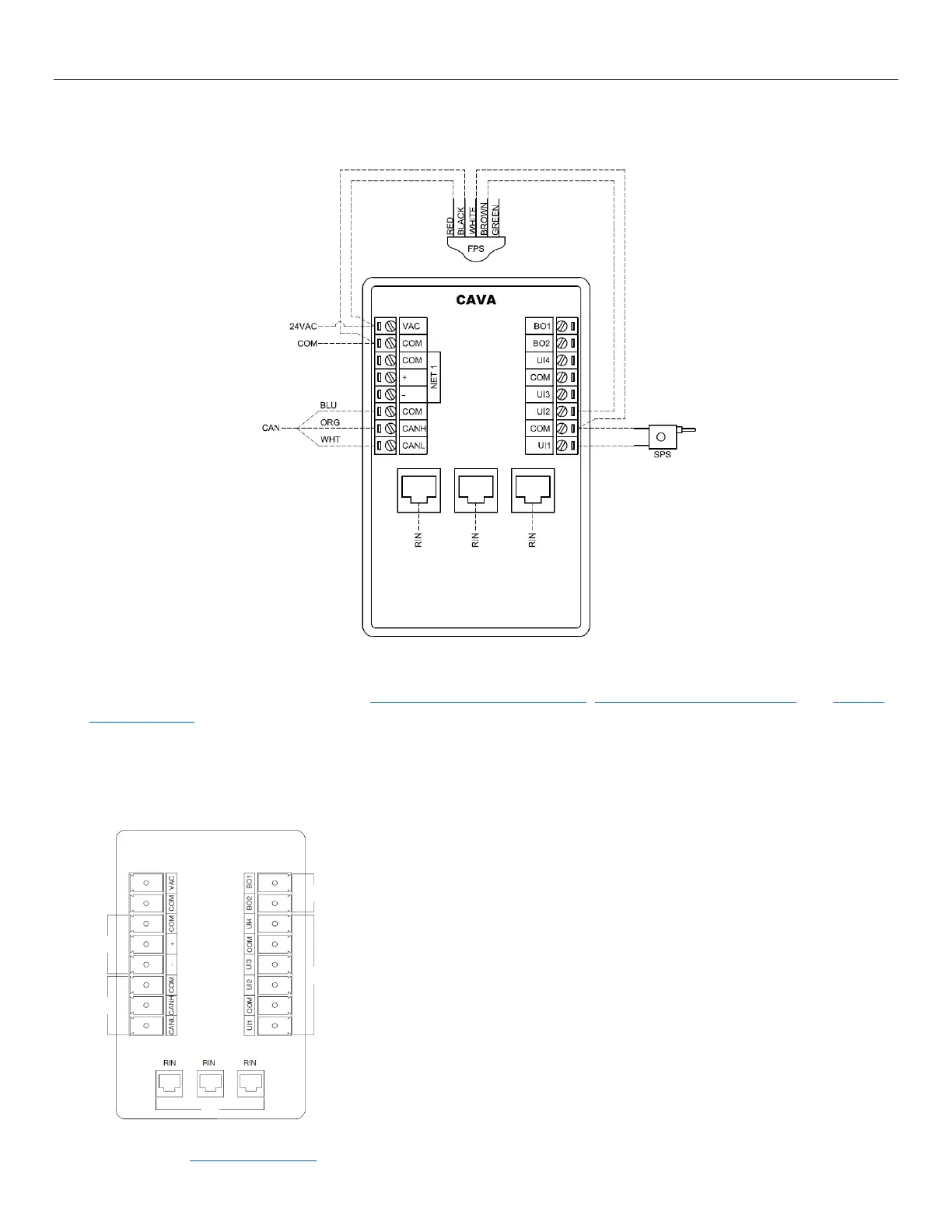
ELECTRICAL INSTALLATION
Wiring
NOTES:
1. For Typical Network Wiring Diagrams, see Room Information Network (RIN), Controller Area Network (CAN), and BACnet
MS/TP Network sections.
2. All wire connections to the Cava™ screw connection terminals must be between 16-26 AWG wire.
3. Current and voltage drop should be taken into consideration when selecting wire gauge.
4. Wiring above may not reflect those required for your project. Refer to your Antec Controls Wiring Diagram Package for
typical wiring recommendations.
Input / Output Usage
Cava™ has native BACnet capabilities, with the connection being made through the NET 1
terminals.
Cava™ can connect to the Fume Hood Valve Module (FVM) and the Sidewall Velocity
Sensor (SVS) through the Controller Area Network (CAN) terminals.
Cava™ can provide a switchable ground binary signal based on a variety of variables and
inputs.
NOTE: The high side of the device should be connected to a 24VAC supply, and the
common of the device should be connected to a Binary Output terminal.
Cava™ includes Universal Inputs that can be any of the following:
• Binary Input (Contact Closure or Active)
• Analog Input (0 to 10 VDC)
• Resistance Input (0-50 kΩ)
Universal Inputs are generally used to connect Sash Position Sensors (SPS) or Fume Hood
The Ethernet Ports can be used to connect Cava™ to other room devices through the Room
Information Network (RIN) and used for setup or service.