18
www.pridemobility.com Icon
WARNING! Do not expose the control console assembly to moisture. In the event it does
become exposed to moisture, do not attempt to operate your scooter until it has dried
thoroughly.
IV. YOUR SCOOTER
CONTROL CONSOLE ASSEMBLY
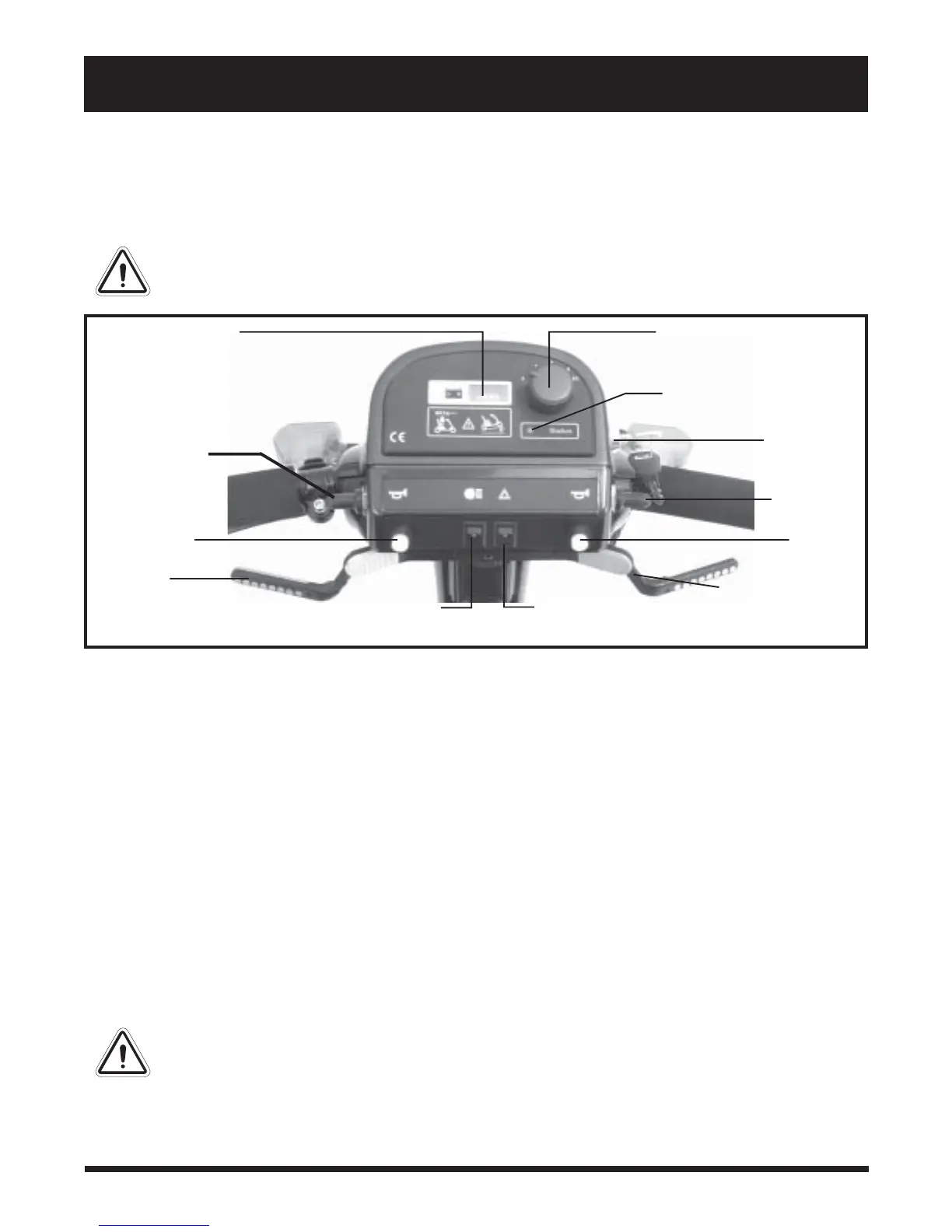
The control console assembly located on the front section houses all of the controls you need to operate
your scooter. See figure 5.
Figure 5. Control Console Assembly
Battery Condition Meter
When the key is fully inserted and turned clockwise to power up your scooter, this meter indicates the approxi-
mate battery voltage strength. For further information on battery charging, see V. “Batteries and Charging.”
Speed Adjustment Dial
This dial allows you to preselect and limit your maximum speed.
On/Off Status LED
When lit this LED indicates that the scooter is powered up.
Key Switch
This switch enables you to power up (turn on) and power down (turn off) your scooter.
! Fully insert the key into the key switch and turn the key clockwise to power up your scooter.
! Turn the key anticlockwise and remove it from the key switch to power down your scooter.
WARNING! If the key is removed from the key switch while your scooter is in motion, the
electronic brakes will engage and your scooter will come to an abrupt stop!
BATTERY CONDITION
METER
THROTTLE
CONTROL LEVER
THROTTLE CONTROL
LEVER
LIGHT
SWITCH
HAZARD LIGHT
SWITCH
SPEED ADJUSTMENT DIAL
KEY
SWITCH
HORN
BUTTON
HORN BUTTON
ON/OFF STATUS LED
TURN INDICATOR
SWITCH
TURN
INDICATOR
SWITCH