Chapter 2 - Specifications
GP-37W3 Series User Manual2-6
When creating your own cable, follow the instructions listed below:
<With RS-422>
• The following pairs of pin #'s must be connected to each other.
#18 (CSB) <—> #19 (ERB)
#21 (CSA) <—> #22 (ERA)
• When connecting the RS-422 cable and the #9 (TRMX) and #10 (RDA) points, a
termination resistance of 100
ΩΩ
ΩΩ
Ω is added between RDA and RDB.
• When making a cable for a Memory Link system, be sure to use a 4-wire type.
<With RS-232C>
• Do not use the following pins: 9 (TRMX), 10 (RDA), 11 (SDA), 15 (SDB), 16
(RDB), 18 (CSB), 19 (ERB), 21 (CSA), 22 (ERA).
• The #1 (FG) terminal should only be connected if it is required by the device being
connected to.
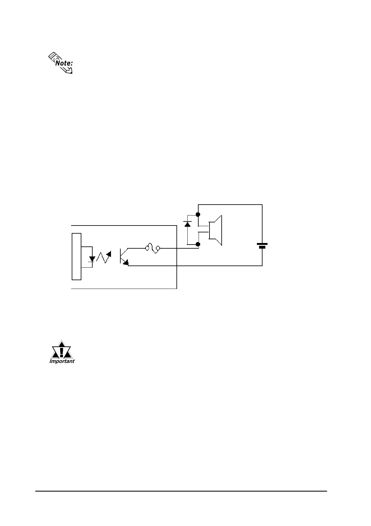
<Buzzer Output>
• #23 (BUZZ GND) and #25 (BUZZ OUT) are used for Buzzer Output.
Optical Isolation
Buzzer
SIO
25pin
SIO
23pin
GP-37W3 unit (internal circuit)
Internal Circuit
Buzzer Output
• This unit’s RS485(RS422) port is not isolated, therefore, it is impor-
tant that you connect the SG/GND (Signal Ground) terminals. If this
is not done, the RS485(RS422) circuit may be damaged.
• Pin 14 (VCC) DC5V output is not protected. To prevent damage or
unit malfunction, be sure to use only the designated level of current.
Can drive a DC5V to
DC24V buzzer at up
to 0.3A
Connect the #1 (FG) terminal only if it is required by a connected device.
 Loading...