Chapter 2 - Specifications
GP-37W3 Series User Manual 2-5
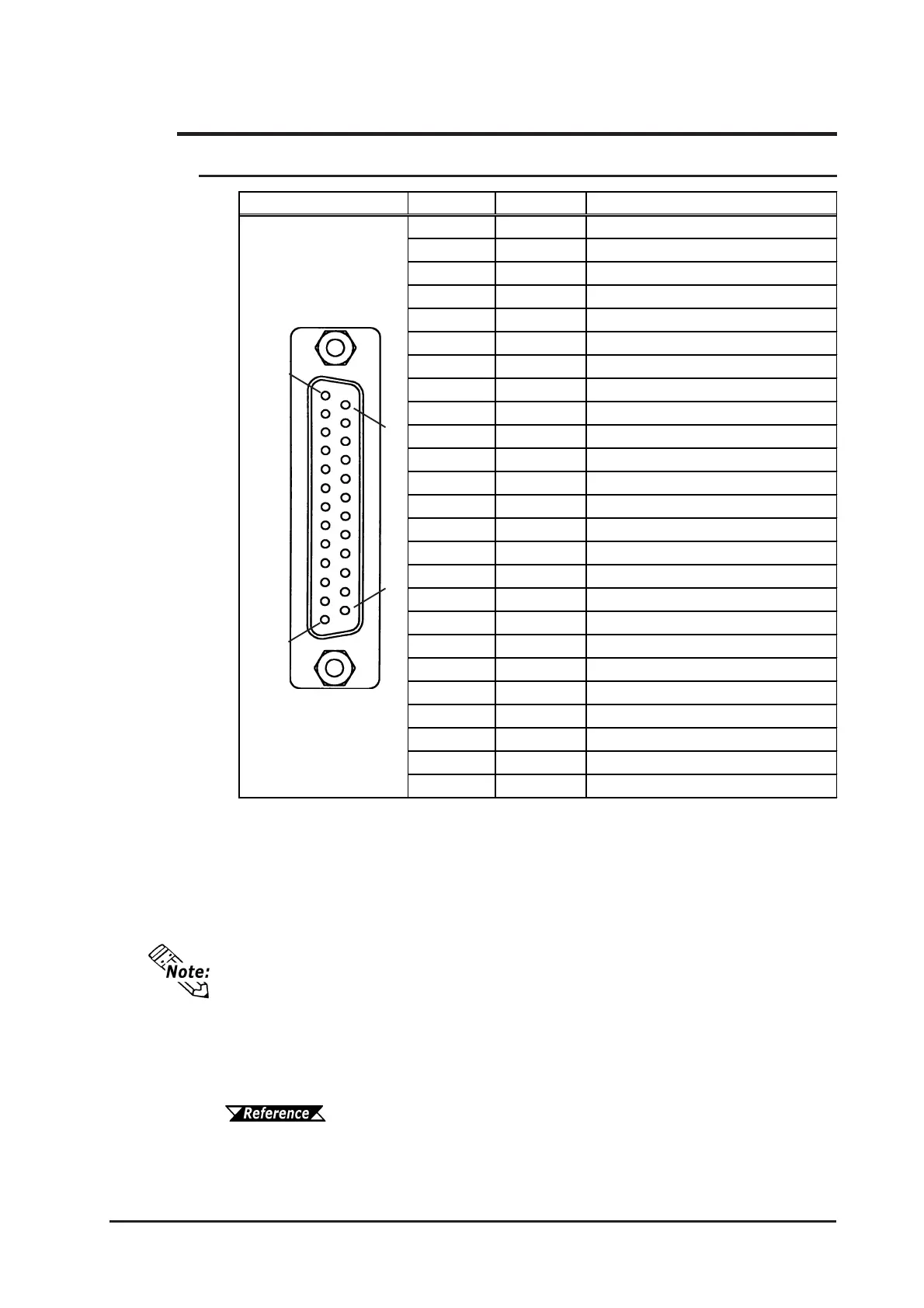
*1 #12 and #13 are RESERVED; do not connect to these pins.
2.3 Interface Specifications
2.3.1 Serial Interface
Recommended Connector: Dsub25pin plug XM2A-2501<made by OMRON>
Recommended Cover: Dsub25pin cover XM2S-2511<made by OMRON>
Dsub25pin cover XM2S-2521<made by OMRON>
Jack Screws: XM2Z-0071<made by OMRON>
Use rough metric type M2.6x0.45 p threads used to secure the cable’s set screws.
Recommended Cable: CO-MA-VV-SB5P x 28AWG <made by HITACHI Cable Ltd.>
To confirm your PLC’s connection specifications
Pro-Designer On-line Help
Pin Arrangement Pin # Signal Name Condition
1 FG Frame ground
2 SD Send data (RS-232C)
3 RD Receive data (RS-232C)
SIO 4 RS Request send (RS-232C)
5 CS Clear send (RS-232C)
6 NC No connection
7 SG Signal ground
8 CD Carrier detect (RS-232C)
9 TRMX Termination (RS-422)
10 RDA Receive data A (RS-422)
11 SDA Send data A (RS-422)
12
*1
RESERVE Reserved
13
*1
RESERVE Reserved
14 VCC 5V±5% output 0.25A
15 SDB Send data B (RS-422)
16 RDB Receive data B (RS-422)
17 NC No connection
18 CSB Clear send B (RS-422)
19 ERB Enable receive B (RS-422)
20 ER Enable receive (RS-232C)
21 CSA Clear send A (RS-422)
22 ERA Enable receive A (RS-422)
23 BUZZ GND External buzzer ground
24 NC No connection
25 BUZZ OUT External buzzer output
1
13
25
14
 Loading...