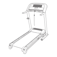
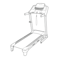
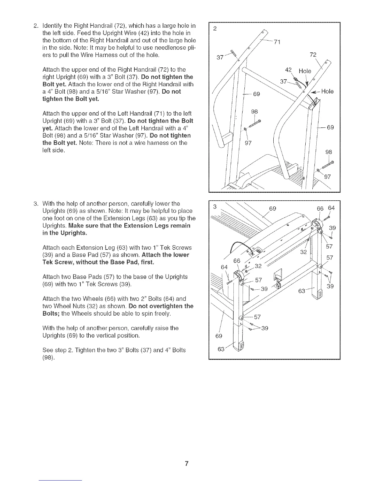
UdentifytheRightHandrail(72),whichhasaUargehoUein
theUeftside,FeedtheUprightWire(42)intothehoUein
thebottomoftheRightHandrailandoutofthelargehoUe
intheside,Note:UtmaybeheUpfuUtouseneedUenosepli-
erstopulltheWireHarnessoutofthehoUe,
AttachtheupperendoftheRightHandrail(72)tothe
rightUpright(69)witha 3"BoUt(37),Donottightenthe
BoJtyet,AttachtheUowerendoftheRightHandrailwith
a 4"BoUt(98)anda 5/16"StarWasher(97),Donot
tightenthe Boltyet,
AttachtheupperendoftheLeftHandrail(71)totheUeft
Upright(69)witha 3"BoUt(37),Donottightenthe BoJt
yet,AttachtheUowerendoftheLeftHandrailwitha 4"
Bolt(98)anda5/16"StarWasher(97),Donottighten
the Boltyet,Note:Thereisnota wireharnessonthe
leftside,
71
42
72
\
Hole
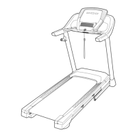
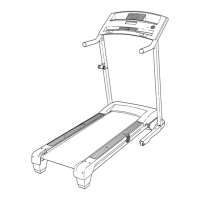
With the help of another person, carefully lower the
Uprights (69) as shown, Note: It may be helpful to place
one foot on one of the Extension Legs (63) as you tip the
Uprights, Make sure that the Extension Legs remain
in the Uprights.
Attach each Extension Leg (63) with two 1" Tek Screws
(39) and a Base Pad (57) as shown, Attach the tower
Tek Screw, without the Base Pad, first,
Attach two Base Pads (57) to the base of the Uprights
(69) with two 1" Tek Screws (39),
Attach the two Wheels (66) with two 2" Bolts (64) and
two Wheel Nuts (32) as shown, Do not overtighten the
Botts; the Wheels should be able to spin freely,
With the help of another person, carefully raise the
Uprights (69) to the vertical position,
See step 2, Tighten the two 3" Bolts (37) and 4" Bolts
(98),
64
69 66 64
',9