4
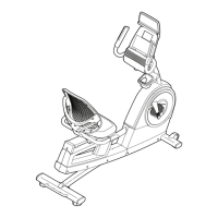
ASSEMBLY
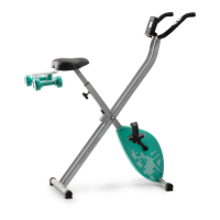
STEP 1
Lift the front of the main frame and t the Front
Stabilizer (65) with 2 x Carriage Bolts (41), 2 x
Curved Washers (36), 2 x Spring Washers (71) and
2 x Cap Nuts (35). Now repeat this process for the
Rear Stabilizer (40).
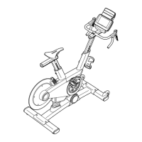
STEP 2
Attach right pedal (26R) on the right pedal crank.
(NOTE: The screw direction is clockwise).
Now repeat this process for the left pedal (26L).
(NOTE: The screw direction is anti-clockwise).
Then mount the pedal straps left and right on the
associated pedals.
Note : The pedals are signed with “L” for left
and “R’ for Right.
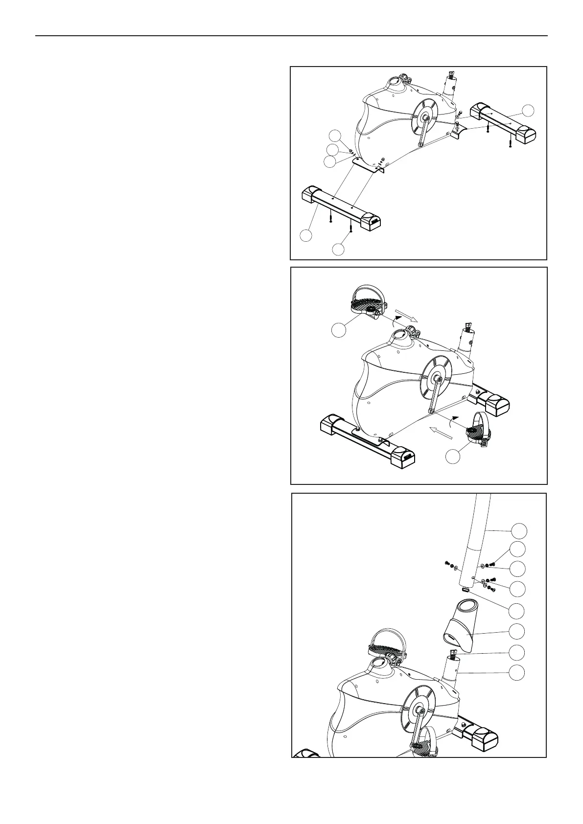
STEP 3
Carefully lift the Handlebar Post (72) until it is verti-
cal. Slide the front plastic cover (68) onto handle-
bar post (72). Join the upper Computer Cable (69)
to the lower Computer Cable (67). Then put the
Handlebar Post into Main Frame, and secure them
with 4 Curved Washers (36), 4 Spring Washers
(71) and 4 Allen Bolts (70).
35
71
40
41
65
36
26L
26R
68
69
71
36
70
67
66
72