10
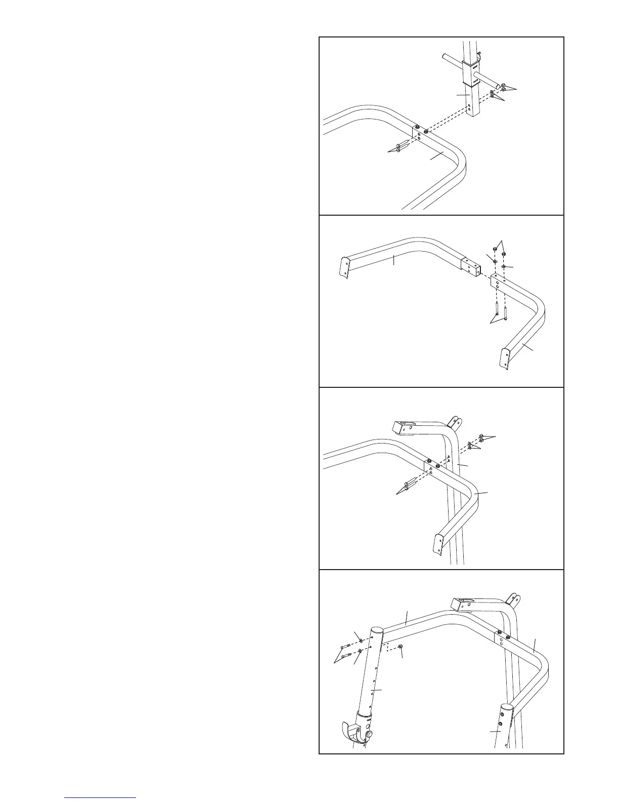
16. Attach the Right Top Frame (69) to the Left Top
Frame (54) with two M8 x 69mm Bolts (58), two
M8 Washers (37), and two M8 Nylon Locknuts
(41).
Make sure that the bolts heads are inside
the hexagonal holes in the Left Top Frame. Do
not tighten the Locknuts.
15. Attach the Rear Upright (33) to the Left Base (46)
with two M8 x 97mm Bolts (72), two M8 Washers
(
37), and two M8 Nylon Locknuts (41). M
ake
sure that the bolts heads are inside the hexag-
o
nal holes in the Left Base. Do not tighten the
Locknuts.
15
46
72
37
33
16
37
37
69
58
33
54
41
17. Attach the Left Top Frame (54) to the Rear
Upright (33) with two M8 x 97mm Bolts (72), two
M8 Washers (37), and two M8 Nylon Locknuts
(41). Make sure that the bolts heads are inside
the hexagonal holes in the Left Top Frame. Do
not tighten the Locknuts.
72
17
37
41
54
18. Attach the Right Top Frame (69) to the Right
Upright (55) with two M8 x 80mm Button Bolts
(70), two M8 Washers (37), and an M8 Nylon
Locknut (41). Do not tighten the Locknut.
Attach the Left T
op Frame (54) to the Left
Upright (4) in the same manner.
T
ighten the bolts and locknuts used in steps
11–12 and 15–18.
70
37
41
55
4
37
69
18
54
4
1