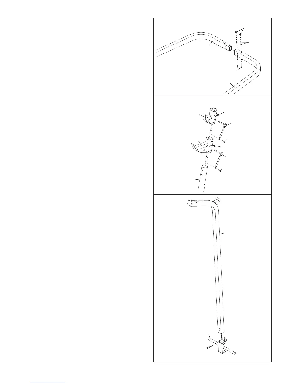
14. Insert the M10 x 20mm Bolt (66) into the Weight
Carriage (62) from the side shown.
Slide the Weight Carriage (62) onto the Rear
Upright (33) as shown.
9
13. Identify the Right Weight Rest (53) and Right
Spotter (9) by the location of the indicated holes.
Attach a Weight Rest Pin (24) to the Right Spotter
(9) with an M4 x 25mm Self-tapping Screw (42).
Slide the Right Spotter onto the Right Upright (55)
and engage the Weight Rest Pin into the Spotter
and Upright.
Attach a Weight Rest Pin (24) and the Right
Weight Rest (53) to the Right Upright (55) in the
same manner.
Repeat this step with the Left Upright (not
shown).
12. Attach the Right Base (47) to the Left Base (46)
with two M8 x 69mm Bolts (58), two M8 Washers
(
37), and two M8 Nylon Locknuts (41). M
ake
sure that the bolts heads are inside the hexag-
o
nal holes in the Left Base. Do not tighten the
Locknuts.
12
37
4
7
4
1
46
58
13
42
9
55
53
42
24
Hole
Hole
24
33
14
62
66