X K 3 1 9 0 –DS3
(2)
Chapter 2 Installation
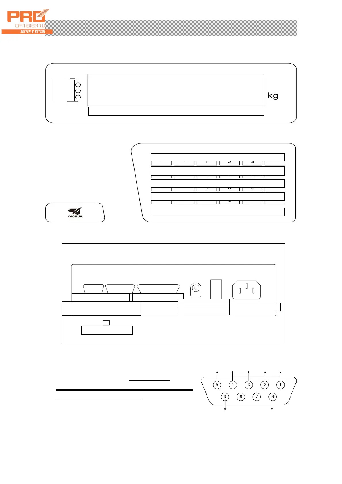
I. Front and Back Function Schematic Diagrams of Indicator
(Figure 2-1) Front Functional Schematic Diagram
(Figure 2-2) Back) Function Schematic Diagram
II. Connection between Load cell and Indicator
XK3190-DS3 is a digital weighing indicator. Therefore,
it can only be connected with digital load cell
(indicator). For easy indication, the product is called
as load cell (indicator) for short.
1. The load cell is equipped with 9 core connector for
connection. Meanings of all pins are marked in Figure
2-3.
(Figure 2-3) Digital load cell interface
Shield -T -R +T +R
+V -V
Battery
Capacit
Internal Code|Auto|Gross Weight|Net Weight|Stable|Tare|Null Position
Address|Calibration| Vehicle No.| Article No.| Save Tare|Check
Angle modulation|Set|Supplementary Printing|Clock| Tare Setting|Input
Angle modulation|Set|Supplementary Printing|Clock| Tare Setting|Input
Self-calibration|Gross/Net Weight| Accumulative Printing|Clear|Weighing
Test|Brightness|Printing|F1|Tare|Zero
XK3190-DS3 Digital Weighing Display Controller
Interface of load cell
Interface of communication and
scoreboard
Interface of printer
Socket of DC power
Power switch
Socket of AC power
Calibration switch