X K 3 1 9 0 –DS3
(3)
2. Load cell interface of XK3190-DS3 adopts the interface mode of four-wire RS485 mode.
Table 2-1-1 Digital Load Cell Connection
III. Connection between Printer and Indicator
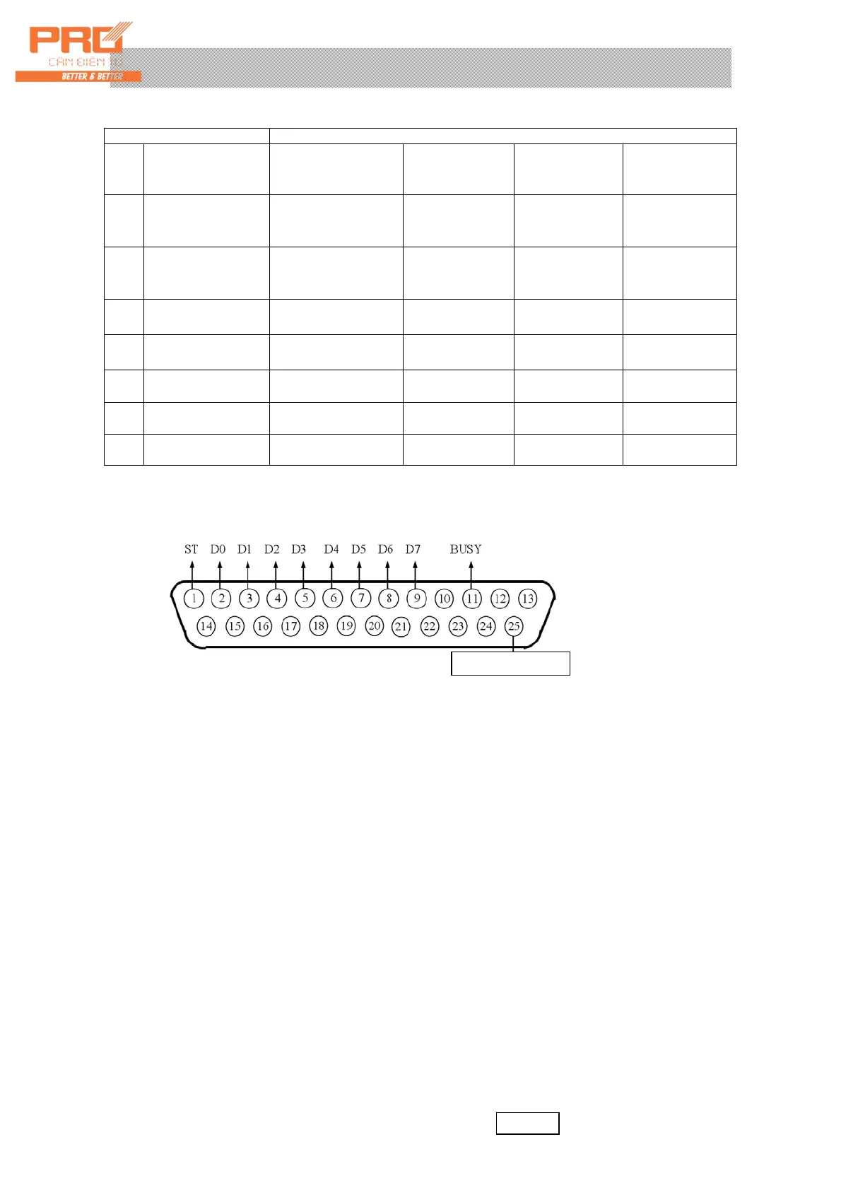
1. The printer is equipped with standard parallel output interface and 25-core RS232 connector
assembly. See definition of its pins in Figure 2-4.
(Figure 2-4) Printer interface signal
2. Printing directions:
▲! The printer may be used only after completing relevant settings. All relevant
paremeters of the printer must be set before using it.
▲! Connection between printing interface output pin of the indicator and the printer must
be accurate without fault. Only dedicated connecting wire for printing may be used.
(Indicator must be connected with printer by appropriative cable accurately.) If wrong
connection occurs, output interface of the indicator or that of the printer and even the
indicator and printer may be damaged.
▲! When using printer, connect all lines accurately at first, then switch on the power of
indicator and at last the power of printer. After use, please turn off the printer first
and then turn off the power of indicator and disconnect all the cables. Any reversed
operation may damage the indicator and printer. Please be careful.
▲! Printers are of various model and parameters, they may be not be compatiable with our
indicator. Please choose printers as remmended.
The printer must be equipped with reliable ground. Otherwise, this may disturb
regular performance of the indicator or even damage the indicator and printer.
IV. Connection between Scoreboard and the Indicator and Their Use
▲ ! Output pin of the scoreboard shall be connected accurately without fault. Error connection
may damage the output interface of indicator or that of scoreboard or even damage the
indicator and scoreboard seriously. The connection requires the use of dedicated connection
wires.
1. Interface of the scoreboard is 15-core RS232 connector (use in common with the serial communication
Indicator Interface Pins Sensor (load cell) Interface Pins …… Color of Corresponding Wire
Pin
No.
Definition Connection Method
Zhonghang Electronic
Measuring Indicators
Co., Ltd.
Guangzhou Electrical
Measuring Indicators
Factory
Ningbo Benui Electric
Co., Ltd. /Ningbo
Board Electric Co.,
Ltd.
2
Signal
transmission
negative
(-T)
Connect
Signal
reception negative
(-R)
Brown White White
4
Signal
transmission
positive
(+T)
Connect
Signal
reception positive
(+R)
Yellow Green Green
3
Signal reception
negative
(-R)
Signal transmission
negative
(-T)
White Yellow Light yellow or
brown
5
Signal reception
positive
(+R)
Signal transmission
positive
(+T)
Blue Blue Blue
6 Positive pole of
power source (+ V)
Connect positive pole
of power source (+V)
Red Red Red
9 Negative pole of
power source (-V)
Connect negative pole
of power source (-V)
Black Black Black
1 Shield Connect the shielded
wire
―― ―― ――
Si
nal
roun
Optional
 Loading...