X K 3 1 9 0 –DS3
(5)
X : D0、D1、D2 – is the position of decimal point ( 0~4 )
Y : D3 — is the symbol of weight ( 1-negative, 0-positive)
D4 — standby
G 18~G16: data of weight (net weight)
Second frame data: the mark bit is 0;
G 15~G8: data of weight (net weight)
Third frame data: the mark bit is 1;
G 7~G0: data of weight (net weight)
G0~G18: constitute the 19 bits binary codes of weight from low to high (net weight)
V. Connection between Serial Communication Interface and the Indicator and Their
Use
▲! Output lead of the communication interface and computer shall be connected accurately. Error
connection may damage the output interface of indicator, communication input interface of computer or
even damage the indicator, computer and corresponding external equipment.
▲! Operation related to computer communication requires necessary computer technology and
capability of programming. Therefore, it shall be participated or guided by professional technician.
Non-professionals are not allowed to connect the indicator.
The indicator XK3190-DS3 is equipped with RS232/RS422 (optional)/RS485(optional) serial
communication interface for communication purpose with computer.
1. Communication interface is equipped with 15 core RS233 connector assembly (shared with scoreboard). See
definition of pins 6, 7, and 8 (RS232) or 1, 2, 3, 4 and 8 (RS422/RS485) in Figure 2-5.
2. All datas are of ASCII code. Every group of data is constitute of 10 bits of data, the first bit is start bit, the 10
th
bit is stop bit and the mid eight bits are data bits. Communication methods are divided into:
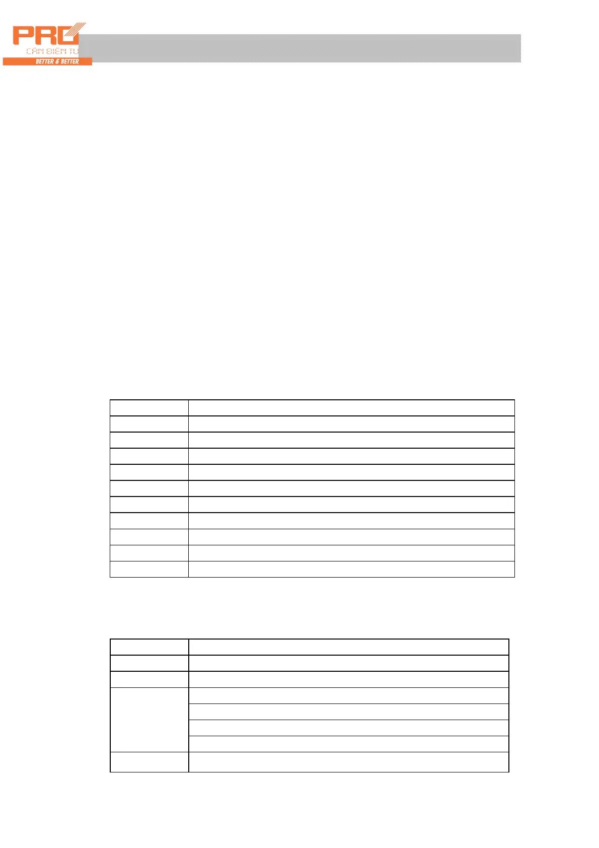
(1) Continuous mode:
Data being sent is the current weight (gross weight or net weight) displayed on indicator. Data of
each frame is comprised of 12 groups of data. See the forms as follows,
Byte X Content and Note
1 02(XON) Start
2 + or - Sign bit
3 Weighing data Higher bit
: Weighing data :
: Weighing data :
8 Weighing data Lower bit
9 Decimal points From right to left (0~4)
10 Xor checking Four higher bits
11 Xor checking Four lower bit
12 03(X0FF) End
Xor =2⊕3⊕……8⊕9
(2). Command mode:
Corresponding data is sent by the indicator by command from host computer. With an command sent
from the host computer, the indicator outputs a frame of corresponding data. Commands sent by host
computer are as follows,
X byte Content and Note
1 02(XON) Start
2 A~Z Serial No. of Address
A~E Command (command) A: Hand shaking
Command B: Reading gross weight
Command C: Reading tare
3
Command D: Reading net weight
4 Xor checking Four higher bits
 Loading...