This document serves as the owner's manual for the UNITED PROARC CORPORATION Positioning System and Accessories, specifically the Model TR-0103 Turning Roll, with serial numbers 2101001 and later, dated January 15, 2021. It provides essential information for installation, operation, and servicing.
Function Description
The TR-0103 Turning Roll is a positioning system designed to rotate workpieces for welding, cutting, or other fabrication processes. It consists of a drive unit and an idler unit, both equipped with rollers to support and turn cylindrical objects. The system allows for adjustable speed and direction of rotation, facilitating precise control over the workpiece's position during operation.
Important Technical Specifications
Model: TR-0103
Input Power: 1 Phase, AC 110 ~ 240V, 50 / 60 Hz
Drive Motor: PMDC Motor, 24V 65W
Turning Capacity: 1,000 kg
Load Capacity (Drive + Idler): 1,000 kg
Speed Range: 80 ~ 1,600 mm/min
Diameter Range:
- Ø 20 ~ Ø 500 mm (G)
- Ø 400 ~ Ø 800 mm (G1)
Roller Type: PU (Polyurethane)
Roller Diameter (E): Ø 200 mm
Roller Width (F): 50 mm
Overall Length (A):
- Drive: 470 mm
- Idler: 450 mm
Overall Width (B):
- Drive: 320 mm
- Idler: 160 mm
Overall Height (C): 334 mm
Roller Center to Base (D / D1):
- Drive: 234 mm
- Idler: 192 mm
Net Weight (Drive / Idler): 54 kg (37 kg / 17 kg)
Gross Weight: 58 kg
The main frame of the TR-0103P (Drive unit) includes components such as axle screws, washers, PU wheels with bearings, spacers, hex nuts, a main drive wheel, joint bearing, internal stud, PMDC motor & connector, gear reducer, worm gear reducer, main wheel assembly, and a motor cover. The TR-0103I (Idler unit) main frame includes axle screws, spacers, roll units (PU wheel + bearing), PU wheels, deep-groove ball bearings, washers, nylon insert lock nuts, and an idler wheel assembly.
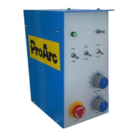
The control box contains a knob, potentiometer, toggle switch, push button, foot switch, power socket, AC power cord (standard, European, Australian, U.K. options), printed circuit board, power supply, grounding copper bar, control box electrical panel, and control box cover.
Usage Features
Operation Penal: The control panel features a Stop button, Power socket, Forward / Reverse switch, Speed adjustment knob, Foot switch, and Power cord.
Installation / Operation:
- Power Cord: Connect to a 100V~240VAC single-phase power supply.
- Power Switch (SW1): "I" for On, "O" for Off.
- Forward / Reverse Switch (SW2): Selects the direction of rotation.
- Stop Button: Press to pause all motion and disable control. Rotate clockwise to reset.
- Speed Adjustment Knob (VR1): Rotate clockwise to increase speed, counter-clockwise to decrease speed.
- Foot Switch (F.S): An alternative type switch. Press once to activate the roller, press a second time to stop it.
- Fuse Holder (Fuse): Provides overload protection.
Main Wheel Adjustment Procedure:
- Step 1: Start the machine and adjust the speed to 50%.
- Step 2: Use a 17mm wrench to adjust the nut in a clockwise direction until the PU roller moves.
- Step 3: Press the rollers with approximately 20-30 kg pressure and check for any slip on the PU rollers.
Maintenance Features
Electrical Safety:
- Ensure the counter, safety device against excess current, and electrical installation are compatible with the machine's maximum power and main voltage.
- The connection (single-phase or three-phase) must be compatible with the cable link's plug.
- The earth connection must never be cut by the protection device against electrical shocks.
- Avoid contact between metal parts and phase/neutral conductors.
- Ensure electrical connections of different machines are properly earthed.
- Before control or repair, switch off and insulate the apparatus.
- Only qualified persons are authorized for electrical installation interventions.
General Maintenance:
- Regularly check the insulation and good condition of apparatus and electrical accessories (taps, cords, coatings, switches, extension cords).
- Maintenance and repair of insulating coatings are crucial.
- Defective accessories should be repaired by a specialist or replaced.
- Regularly check the adjustment and non-heating of electrical connections.
Individual Safety:
- Operators must wear appropriate protective clothing and gear.
- Avoid contacting connected or accidentally connected metal parts.
- Wear leather gloves with gauntlet.
- Safety clothes, gloves, apron, and safety shoes protect against burns, projections, and slag.
Gases and Fumes:
- Gases and fumes from plasma cutting or welding are hazardous.
- Ensure adequate ventilation to remove fumes from the breathing area.
- Use an air-supplied respirator if ventilation is insufficient.
Fire Safety:
- Oil or grease with oxygen can ignite violently. Keep cylinders, valves, couplings, regulators, hoses, and apparatus clean and free from oil and grease.
- Do not handle oxygen cylinders with oily hands or gloves.
- Do not allow oxygen to contact oily or greasy surfaces.
- Do not use oxygen as a substitute for compressed air.
- Remove combustibles from the work area or provide a fire watch.
- Do not cut containers that have held combustibles. Remove all flammable materials that could be ignited by sparks.
Noise:
- Noise can cause permanent hearing loss.
- Wear proper protective ear muffs or plugs.
- Ensure others in the operating area are protected from noise.
Protection Goggle:
- Welding radiation can cause permanent sight damage.
- Eyes protection goggles are recommended.
Limited Warranty:
UNITED PROARC CORPORATION warrants new equipment to be free from defects in material and workmanship, provided it is installed and operated according to the manual. The obligation is limited to repair or replacement of defective parts, based on FOB Taiwan. The company is not liable for consequential damages. This warranty supersedes all previous ProArc warranties and excludes consumable parts used in normal operation.