18
Balanced Bridging Kit
21
3
12
3
12
3
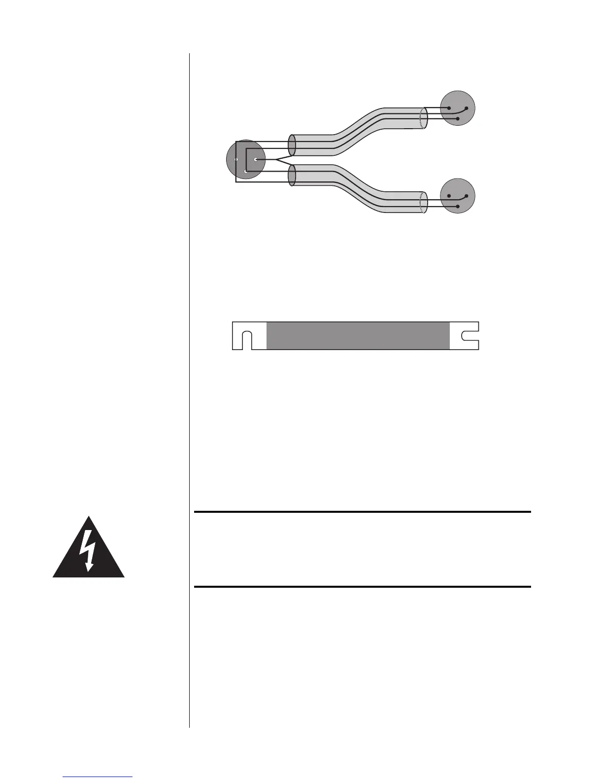
Female XLR Input
Pin 1: signal ground
Pin 2: signal + (non-inverting)
Pin 3: signal – (inverting)
Male XLR Output (normal)
Pin 1: signal ground
Pin 2: signal + (non-inverting)
Pin 3: signal – (inverting)
Male XLR Output (inverted)
Pin 1: not used (floated)
Pin 2: signal – (inverting)
Pin 3: signal + (non-inverting)
Balanced Bridging
Input Adapter
(pin configuration)
Bridging Output Adapter
(not drawn to scale)
(shield not connected)
The “normal” leg of the Madrigal Balanced Bridging Input Adapter will be marked
with a red stripe to indicate positive polarity, and the inverted leg will be marked
with a black stripe to indicate inverted polarity (corresponding to the red and
black terminals of your loudspeaker).
The Balanced Bridging Output Adapter is simply a heavy-gauge copper bar (sil-
ver- and gold-plated) used to strap two of the output ground terminals together.
This establishes a common reference for the amplifier and completes the circuit
that includes the loudspeakers.
Important! Do not attempt to operate your amplifier in a bridged mode
without first strapping the black output terminals together.
Failure to establish a common ground reference between the
two channels can damage your amplifier by forcing
significant currents to flow where they do not belong!
To bridge your amplifier using a balanced input signal, follow these steps:
1 DISCONNECT YOUR AMPLIFIER FROM EVERYTHING
Start with your amplifier totally disconnected from inputs, outputs, and AC
power. It is always best to power down an amplifier before changing con-
nections; here you are also changing its basic configuration, making this
step essential.