www.usaprocom.com
200279-01A6
PROPANE/LP GAS INSTALLATION
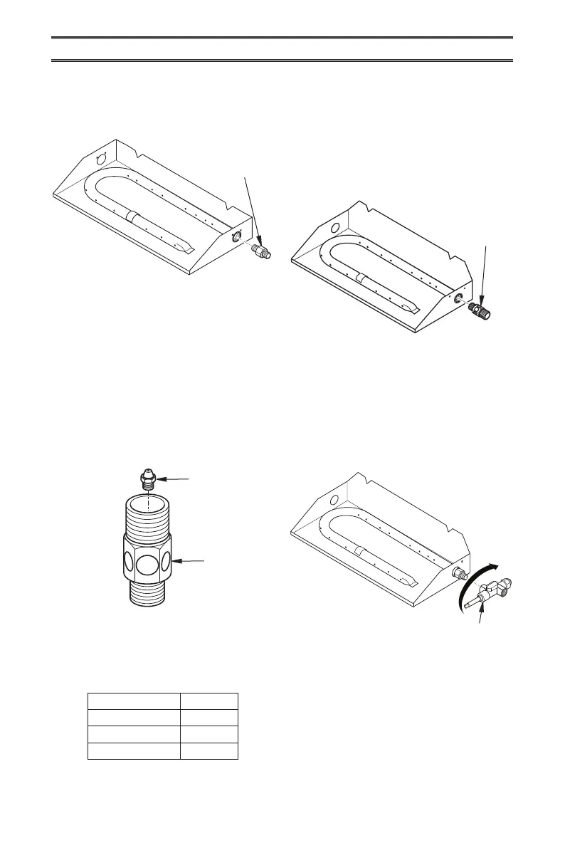
1. Remove the natural gas burner inlet tting
from the burner pan assembly as shown
in Figure 6. DO NOT remove the orice
from this tting.
IMPORTANT: For an 18" or 30" log set, use
a 10 mm socket or nut driver to remove
the orice from the propane/LP burner
air mixer.
3. Using pipe sealant on the thread of the
larger end of tting, screw the propane/
LP burner air mixer through hole and into
burner manifold as shown in Figure 8.
Tighten using a wrench.
Figure 6
Figure 7
Figure 8
Burner Inlet
Fitting for
Natural Gas
IMPORTANT: If you have a 24" log set,
then the 24" propane/LP orice, shown
in the table below, is already installed in
the propane/LP burner air mixer. Proceed
to step 3.
2. The propane/LP burner air mixer included
in this kit has 6 holes and must be used to
replace the natural gas inlet tting. Be sure
to use the correct propane/LP orice for
your appliance. This kit contains additional
orices as shown in the table below.
IMPORTANT: The number stamped on ori-
ces correspond to each respective size
log set as indicated by model numbers as
shown in table below.
Model # Orice #
18" Vented Logs 205
24" Vented Logs 225
30" Vented Logs 242
Figure 9
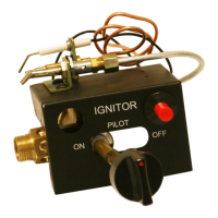
Gas Control Valve
Propane/LP
Burner Air
Mixer
Propane/LP
Burner Air
Mixer
Propane/LP
Orice
4. Thread the gas control valve onto the
burner air mixer. Use pipe sealant on
the male threads of the burner air mixer.
Hold the burner air mixer with a wrench
to prevent overtightening the connection
to the burner. Make sure the control rod
is facing the front as shown in Figure 9.