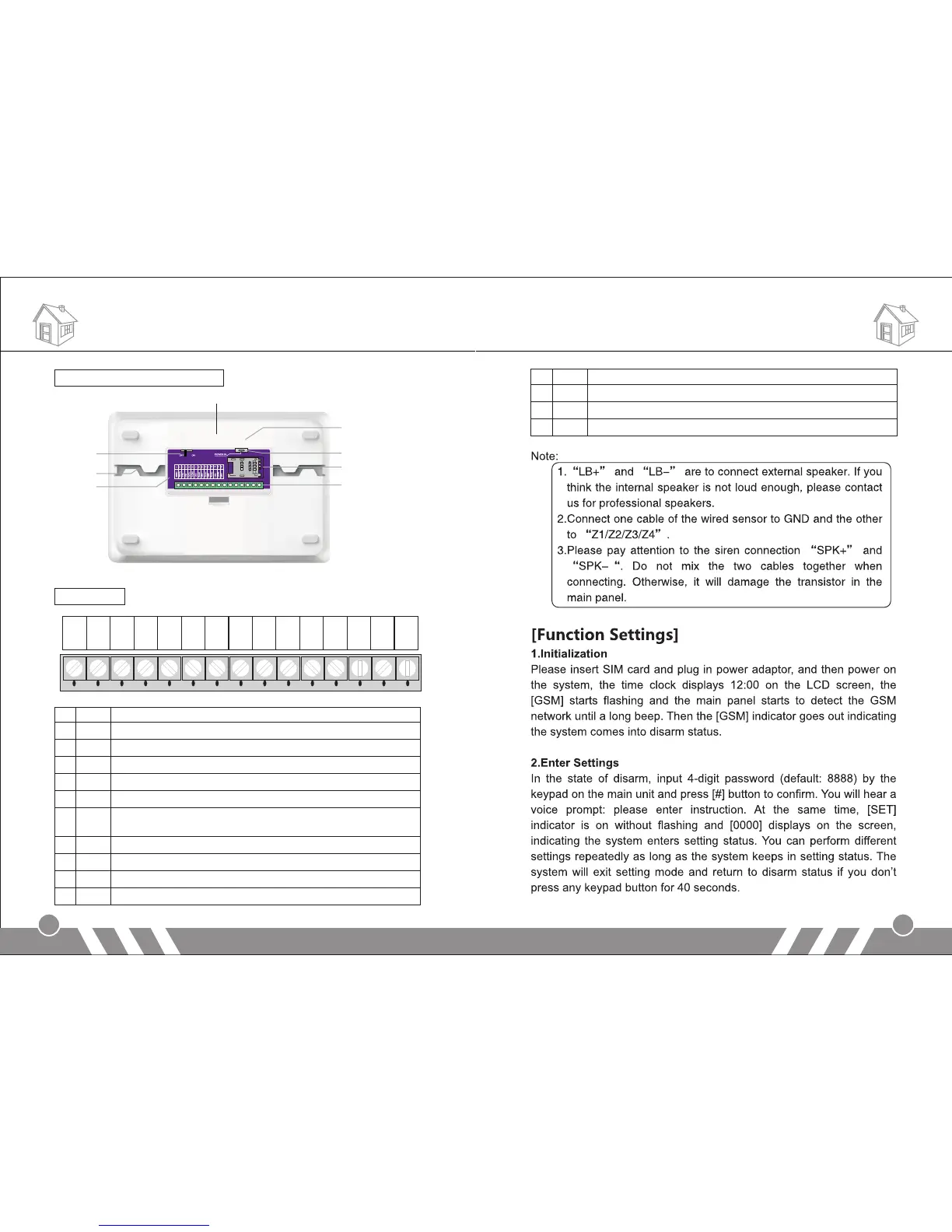
Back cover schematic diagram:
Wired ports:
Function Settings
3
4
Tamper Alarm Button
Power Switch
Lead Wire Slot
PCB
Fix Bracket
DC 12V Input
SIM Card Socket
Wired Ports
SPK+
SPK-
LB+
LB-
GND
P2
Z1
GND
GND
Z3
Z4
P1
Z2
GND
GND
1 2 3 4 5 6 7 8 9 10 11 12 13 14 15
1 SPK+ Positive of siren (red cable)
2 SPK- Negative of siren (black cable)
3 LB+ Positive of two-way speaker (red cable)
4 LB- Negative of two-way speaker (black cable)
5 P1 12V output by remote control. (please refer to Operation Instruction part)
6 GND Ground
7 P2 Linkage output port 2. There will be 12V output once the system is
armed, and be off once it’s disarmed.
8 GND Ground
9 Z1 Wired sensor 1 (zone number: 95)
10 GND Ground
11 Z2 Wired sensor 2 (zone number: 96)
12 GND Ground
13 Z3 Wired sensor 3 (zone number: 97)
14 GND Ground
15 Z4 Wired sensor 4 (zone number: 98)
Alarm Host Diagram