19
Symptom Possible Cause(s) Corrective Action
Heater ignites but MAIN PCB
assembly shuts heater off
after a short period of time.
(Indicator Lamp is flickering
and room temp. display
indicates “E1”)
Heater will not ignite but
motor runs for a short period
of time. (Indicator Lamp is
flickering and room temp.
display indicates “E1”)
Fan does not turn when
heater is plugged in and
power switch was in the “ON”
position. (Indicator Lamp is on
or flickering)
(Indicator Lamp is flic
kering
and room temp. display
indicates “E2”)
(Indicator Lamp is flickering
and room temp. display
indicates “E3”)
Heater will not turn-on
(Indicator Lamp is off)
1. Wrong pump pressure
2. Dirty Air Output, Air Intake or Lint Filter
3. Dirty Fuel Filter
4. Dirt in Nozzle
5. Dirt Photocell Lens
6. Photocell Assembly not Properly Installed
(not seeing the flame)
7. Bad electrical connection between photocell
and MAIN PCB Assembly
8. Defective photocell
1. No fuel in tank
2. Wr
ong pump pressure
3. Carbon deposits on spark plug and/or
improper gap
4. Dirty fuel filter
5. Dirt in Nozzle
6. Water in fuel tank
7. Bad electrical connection between igniter
and MAIN PCB Assembly
8. Igniter wire is not attached to spark plug
1. Thermostat setting is too low
2. Bad electrical connection between motor and
MAIN PCB Assembly
1.
Sensor Failure
1. Thermostat switch failure 1. Replace Switch.
See wiring Diagram, page 13
1. Temperature limit safety device is overheated
2. No electrical power
3. Blown fuse
4. Bad electrical connection be
tween
temperature limit safety device and
PCB board
1. See Pump Pressure Adjustment, page 11
2. See Air Output, Air Intake and Lint Filters,
page 8
3. See Fuel Filter, page 11
4. See Nozzle, page 9
5. Clean Photocell Lens, page 10
6. Make sure photocell boot is properly seated in
bracket, Page 10
7. Check electrical components. See Wiring
Diagrams, page 13
8. Replace Photocell, page 10
1. Fill tank with kerosene
2. See Pump Pressure Adjustment, page 11
3. See Spark Plug, page 9
4. Se
e Fuel Filter, page 11
5. See Nozzle, page 9
6. Flush fuel tank with clean kerosene, page 7
7. Check electrical components. See Wiring
Diagram, page 13
8. Attach igniter to spark plug. See Spark Plug,
page 9
1. Turn thermostat control knob to a higher
setting
2. Check electrical connections. See Wiring
Diagram, page 13
1.
page 13
Replace sensor. See Wiring Diagram,
1. Turn power switch to “OFF” and allow to cool
(about 10 min.)
2. Check to insure heater cord and extension
cord are pl
ugged in. Check power supply
3. Replace safety fuse in PCB board. See
Replacing Fuse, page 12
4. Check electrical connections. See Wiring
Diagrams, page 13
Troubleshooting Chart
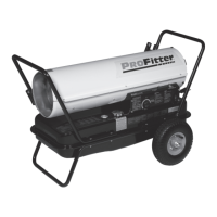
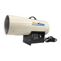
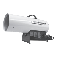
ProFitter
TM
Operating Instructions and Parts Manual
For Technical Support or Troubleshooting, Call: 1-877-447-4768, 8:30 am - 4:30 pm CST www.ghpgroupinc.com
Models KFA50PF, KFA75PF, KFA125PF,
KFA170PF and KFA210PF
NEVER LEAVE THE HEATER UNATTENDED WHILE BURNING!