Assembly (Continued)
FOR MODELS KFA50PF AND
KFA75PF ONLY
FOR MODELS KFA125PF, KFA170PF
AND KFA210PF ONLY
TOOLS REQUIRED
5
Figure 7 – Handle and Cord Wrap
Installation KFA50PF and
KFA75PF only
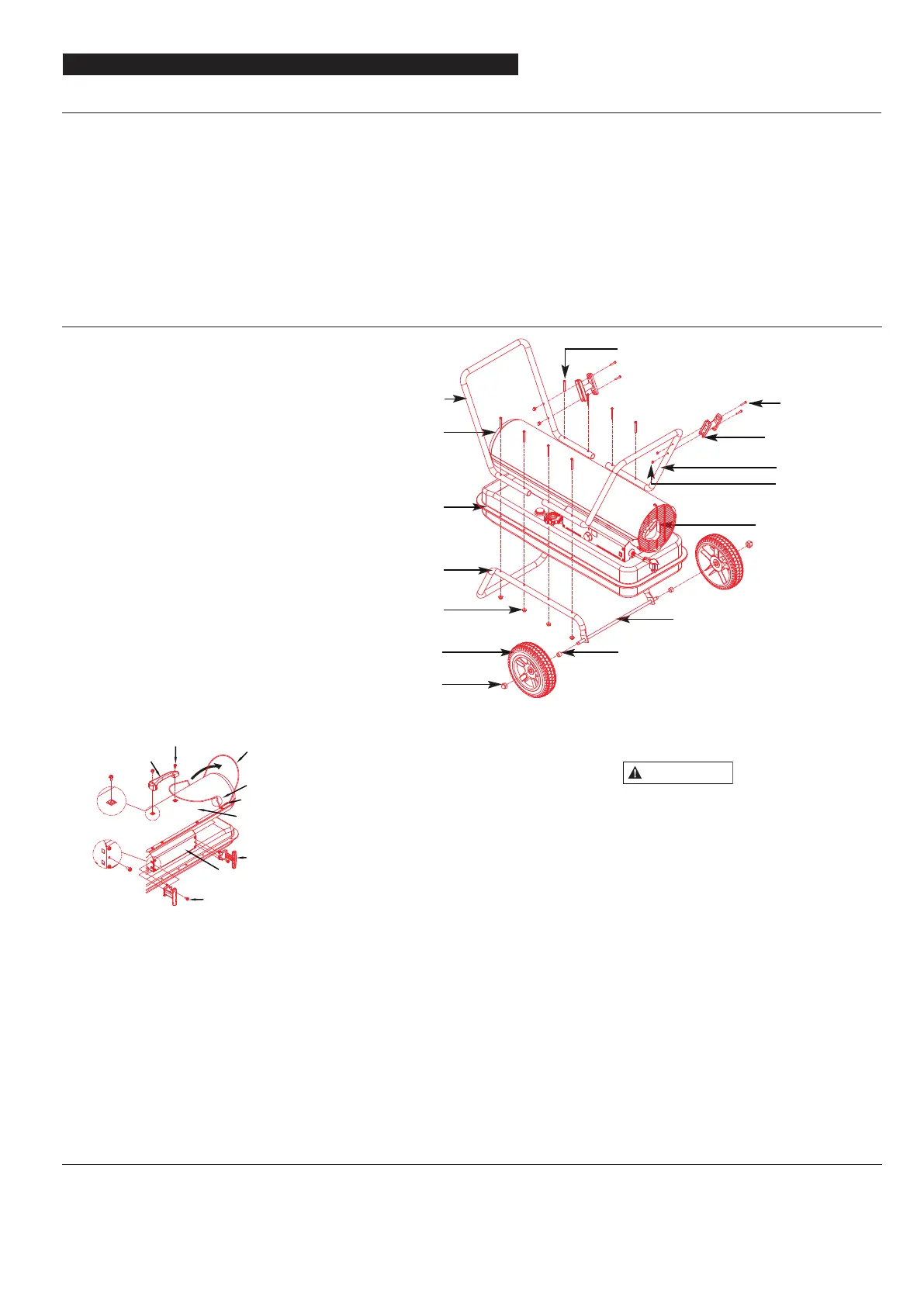
Figure 8 – Models KFA125PF, KFA170PF and KFA210PF Assembly
- Medium Phillips Screwdriver.
- 3/4 inch socket or adjustable wrench
Assembling Handle & Wheel and
Cord Wrap
1. Slide threaded axle through the rear
sectioon of the wheel support frame.
ProFitter
TM
Operating Instructions and Parts Manual
For Technical Support or Troubleshooting, Call: 1-877-447-4768, 8:30 am - 4:30 pm CST www.ghpgroupinc.com
Models KFA50PF, KFA75PF, KFA125PF,
KFA170PF and KFA210PF
NEVER LEAVE THE HEATER UNATTENDED WHILE BURNING!
2. Slide one axle bushing on to each side
of the axle. Slide one wheel on to each
side of the axle. Attach one cap nut on
to each side of the threaded axle and
tighten well.
3. Place heater on wheel support frame.
Align the holes on fuel tank flange
with holes on wheel support frame.
4. Position the Handles on top of fuel
tank flange.
Insert screws through handles, fuel
tank flange and wheel support frames
as shown in Figure 8 and attach nut
finger tight after each screw is inserted.
5. Align the hole on the handles with the
mounting hole on the Cord Wrap.
Insert Scre
ws through Cord Wrap,
handles and attach nut finger tight
after each screw is inserted.
6. After all screws are inserted, tighten
nuts firmly.
Do not operate
heater without
support frame fully assembled to tank.
FUELS
For optimal performance of this heater,
it is strongly suggested that 1-K kero -
sene be used. 1-K kerosene has been
refined to virtually eliminate contami -
nants, such as sulfur, which can cause a
rotten egg odor during the operation
of the heater. However, #1/#2 diesel/fuel
oil, JET A or JP-8 fuels may also be used if
1-K kerosene is not available. Be advised
that these fuels do not burn as clean as
1-k kerosene, and care should be taken
to provide more fresh air ventilation to
accommodate any added contaminants
CAUTION
Front Handle
Hot Air Outlet
Wheel
Cap Nut L
Cap Nut S
Fuel Tank Flange
Nut
Wheel Support
Frame
Flange Screw
Cord Wrap
Screw
Rear Handle
Air Inlet
Threaded Axle
Wheel Bushing
TOOLS REQUIRED
- Medium Phillips screwdriver.
1. Lift front guard for arrow direction
and make sure that guard’s wedged
portion fits into the slit hole on the
upper housing.
2. Remove the pre-assembled screws on
the shell upper and side cover.
3. Align the holes in upper housing
withtwo mounting holes on the
handle asshown in Figure 7.
4. Secure handle with the screws
removed.
5. Insert cord wrap into the rectangle
holes on the supporter and align the
hole on the cord wrap with the
mounting hole on the side cover as
shown in Figure 7.
6. Secure cord wrap with the screws
removed.
Handle
Screw
Front Guard
Wedged
Slit Hole
Side Cover
Cord Wrap
Screw
Shell Upper
Remove Screws
Remove Screws
Portion