11
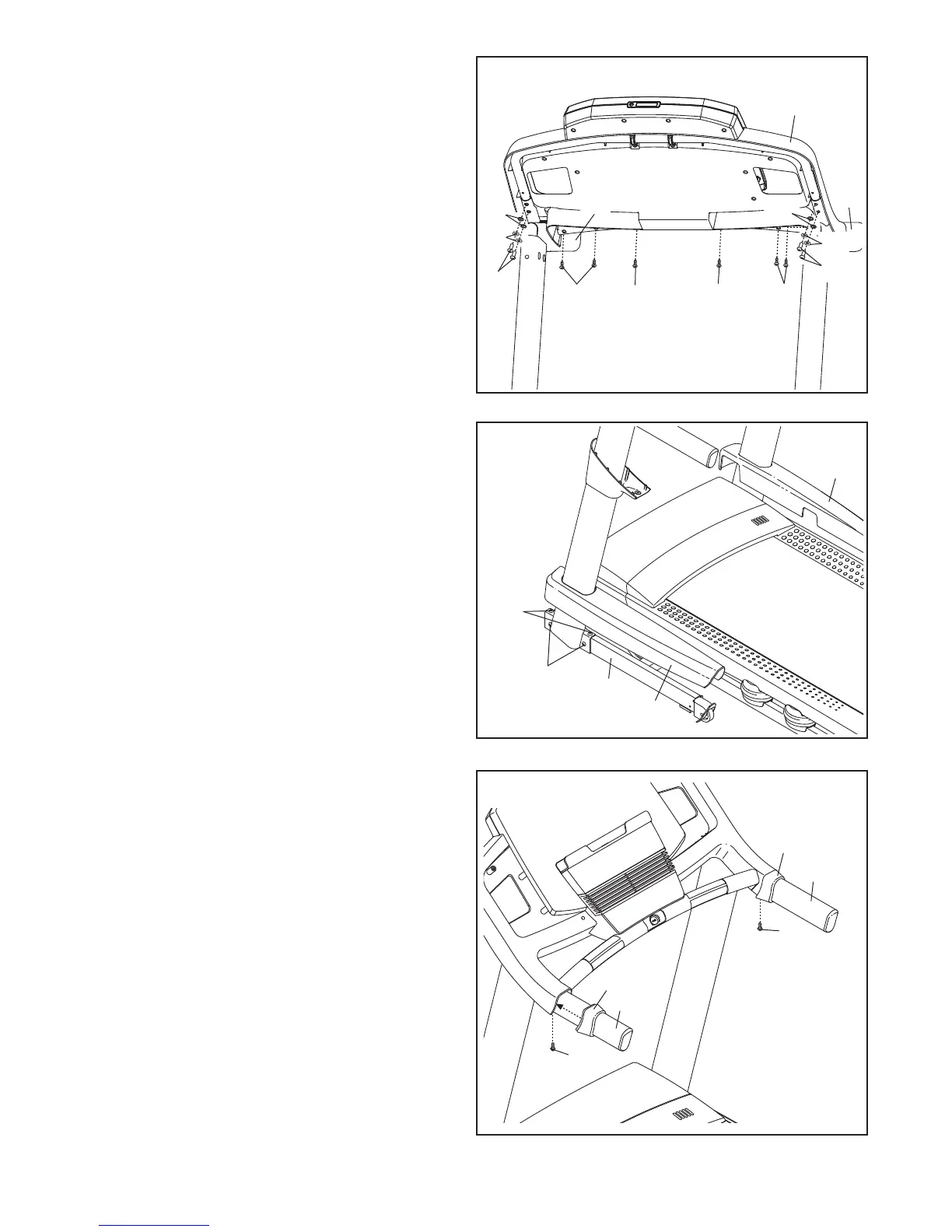
12. Firmly tighten the four the 3/8" x 2 3/4" Bolts (7)
and the four 3/8" x 1 1/4" Bolts (8) (only one
side is shown).
Press the Left Base Cover (82) and the Right
Base Cover (83) onto the Base (94) until they
snap into place.
12
83
8
82
94
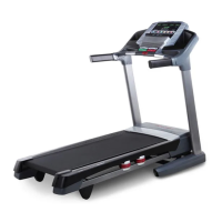
11. Set the console assembly on the Left Handrail
(88) and the Right Handrail (87). Be careful not
to pinch any wires. Insert the excess Upright
W
ire (not shown) into the Left Handrail.
A
ttach the console assembly with six #8 x 1/2"
Screws (1) and four 1/4" x 1/2" Bolts (36) with
four 5/16" Flat Washers (113) and four 1/4" Star
Washers (35) as shown. Start all six Screws
and all four Bolts, and then tighten each of
them.
See step 7. Fully tighten the four 5/16" x 1"
Bolts (5) and the two 5/16" x 1 1/4" Bolts (4).
3
5
88
1
11
Console
Assembly
1
7
87
36
1
1
36
13. Slide the Left Handrail Cover (85) onto the Left
Handrail (88). Slide the Right Handrail Cover
(86) onto the Right Handrail (87). Attach the
Handrail Covers with two #8 x 1/2" Screws (1).
13
85
86
1
1
87
88
35
113
113