1. Before beginning, make sure that you have read
and understood the information on page 4.
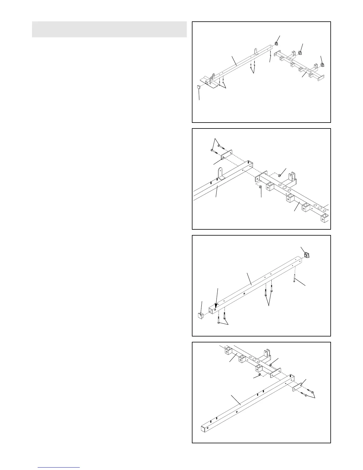
Open the parts bag labeled “FRAME ASSEMBLY.”
Press a 2” Square Inner Cap (28) into each end of
the Butterfly Base (4) and into the indicated locations
on the Weight Base (5).
Insert four 5/16” x 2 1/2” Carriage Bolts (92) and a
3/8” x 3 3/4” Carriage Bolt (85) into the indicated
holes in the Butterfly Base (4). Place the Butterfly
Base flat on the floor. Note: If the Bolts fall out,
secure them by putting a piece of tape over the
head of each Bolt.
1
3. Press a 2” Square Inner Cap (28) into each end of
the Press Base (6). Turn the Press Base so the indi-
cated welded tube is near the top.
Insert four 5/16” x 2 1/2” Carriage Bolts (92) and a
3/8” x 4” Carriage Bolt (104) into the indicated holes
in the Press Base (6). Note: The 3/8” x 4” Carriage
Bolt will be tipped at an angle.
3
4
5
Frame Assembly
92
4
5
28
85
28
28
92
28
64
6
89
5
92
6
28
Welded
Tube
28
104
92
64
94
2
5
4
89
64
94
64
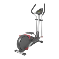
2. Attach the Weight Base (5) to the Butterfly Base (4)
with two 5/16” x 2 3/4” Bolts (89), a Support Plate
(94), and two 5/16” Nylon Locknuts (64).
4. Attach the Press Base (6) to the Weight Base (5) with
two 5/16” x 2 3/4” Bolts (89), a Support Plate (94),
and two 5/16” Nylon Locknuts (64).