9
Connection | Connecting the digital inputs
Assembly and connection manual | Agrónic 4500
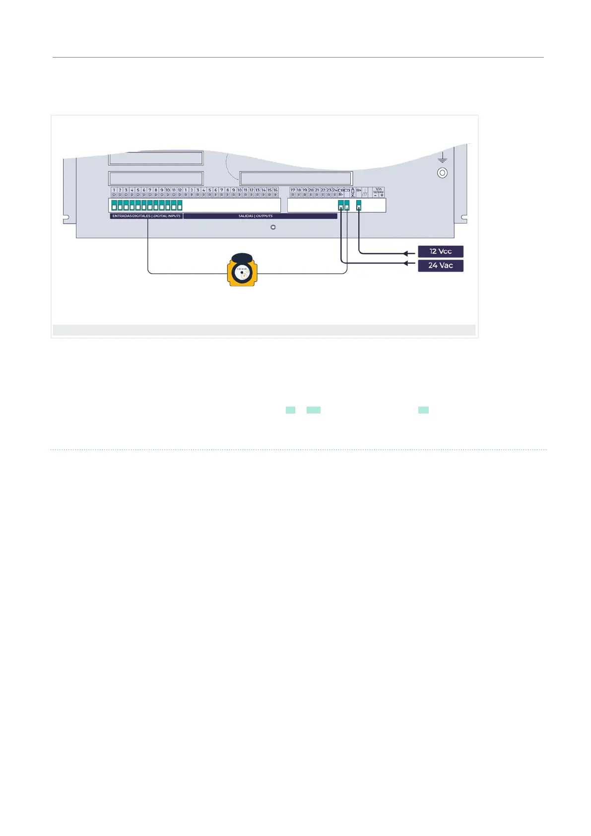
4.3. CONNECTING THE DIGITAL INPUTS
4.4. CONNECTION OF THE OUTPUTS
Both the digital inputs and the relay outputs are exter-
nally powered at 12 Vdc or 24 Vac.
The digital inputs are galvanically isolated by optocou-
plers from the rest of the circuit.
All the outputs are prepared to work both at 12 and 24
volts in alternating or continuous (do not power with
voltages higher than 30 volts).
For 24 Vac operation, an external transformer with 24
Vac output with double insulation must be available
according to the UNE EN61010 standar.
The input for powering the outputs is marked as “R+”
and “R-”.
The “AUX” terminal corresponds to the “R+” input
passed fhrough the power supply protection. It is used
to connect manual control auxiliary elements and relay
extensions.
The contacts of the devices connected to the digital
inputs must be free of voltage.
The controller has 12 digital inputs on the base, indicated
as D1 to D12 and a common marked as CD.
The solenoids of the electricvalves, the relays or the con-
tactors are connected between a common output “CR”
and the corresponding output between “R1” to “R104”.
The outputs are isolated from the internal circuit by
relays and protected by a varistor in each one.
The power supply to the outputs and the sensors are
protected by a self-resetting thermal fuse, also in the
section “Consult - Agrónic” it will indicate whether or
not there is voltage for the outputs. When there is a short
circuit in any of the outputs, the fuse will enter automa-
tically, limiting the output until the short circuit ends.
Digital inputs