Consult a licensed electrician or RV technician for installation assistance 814420H
Inverter Specifications
*All ratings at 25 °C unless otherwise listed
SPECIFICATIONS
PHYSICAL SPECIFICATIONS TRANSFER SWITCH
PD1610 PD1618 PD1620
PD1610 PD1618 PD1620
Dimensions
L:11.2”(284mm)
W:6.7”(170mm)
H:4.0”(101mm)
L:15.0”(381mm)
W:7.9”(200mm)
H:4.0”(101mm)
L:15.0”(381mm)
W:7.9”(200mm)
H:4.0” (101mm)
Transfer Voltage 95 - 135 VAC
Transfer Time < 50 msec
Net Weight 7 lbs (3.2 kg)
11 lbs (5.0 kg) 11 lbs (5.0 kg)
Pass Through
Ampacity
20 AAC
30 AAC
AC OUTPUT DC INPUT
PD1610 PD1618 PD1620
PD1610 PD1618 PD1620
Waveform Pure Sine Wave Nominal Voltage 12.0 VDC
Output
Voltage
120
VAC
Under-Voltage
Shutdown
10.5
VDC
Max Power
(Cont)
1000W
1800W 2000W
Under-Voltage
Restart
12.0 VDC
Max Power
(Peak)
2000W
3600W 4000W
Over-Voltage
Shutdown
15.5 VDC
Frequency 60 Hz
Over-Voltage
Restart
15.0 VDC
Peak
Efficiency
90%
Max Current @
max load
100 ADC 180 ADC 200 ADC
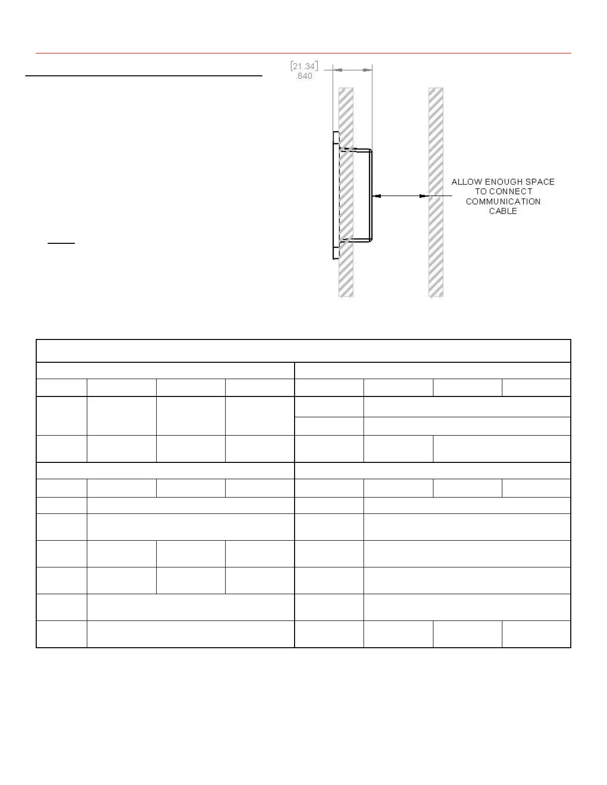
Installing the remote display on the wall
1. Place the template on the wall (See Figure 10).
2. Measure and mark the wall for the opening to be cut for re-
mote control.
3. Mark the corners of the recess outline on the wall.
4. Measure and mark the two mounting holes for the two
screws on the wall.
5. Cut along the recess outlines on the wall to make a hole for
the remote control.
6. Pre-drill the mounting holes appropriate for mount screws
(not provided) that will be used.
7. Connect the communication cable to the RJ9 port on the in-
verter and the remote control (see Figure 2).
8. Mount the remote panel unit on the wall.
Note:
Ensure that there are no
Obstructions present, such as:
- Pipes
- Insulation
- Electrical Wiring
Ensure that there is at least 1” (25.4 mm) of space for communication cable.
Figure 9
Mounting Diagram
Recommended GFCI for use with PD1610 Inverter:
Leviton GFTR2 (20A), Eaton SGF20 (20A), Bestten USP-20A-20-PKB (20A), Hongki TST20 (20A),
Zhangjiagang City Barep Technology Co. YGH-094 (20A),
Recommended GFCI for use with PD1618/20 Inverter:
Siemens QF130A (30A)