Rev: 05.21.18 Page 8
EuroLoft™ Bed Lift (Overhead) OEM
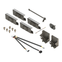
Stabilizer Channel Guides
NOTE: Prior to installing the stabilizer channel guides, the excess length of the stabilizer channel guides
can be removed by measuring the length starting from the top of the roller guide assembly at the
fully retracted position to the bottom of the roller guide assembly at the fully extended position.
NOTE: If installing on a unit with aluminum backing in the wall, use a minimum size of #10 x 1" self-tapping
screws. If installing on a unit with wood backing in the wall, use a minimum size of #10 x 1" self-
drilling screws.
1. Make sure the bed frame is in the fully extended position.
2. Take the top end of the stabilizer channel guide (Fig. 17B) and place under the roller track assembly
(Fig. 17A).
3. Guide the roller track assembly into the stabilizer channel guide. Raise the stabilizer channel guide up
to the desired height.
4. Install three #10 x 1" screws through the stabilizer channel guide; top, middle and bottom, inside the
middle of the stabilizer channel guide (Fig. 18A) and into the wall of the unit.
5. Repeat steps 1-4 for the opposite side.
Fig. 17 Fig. 18
B
A
A
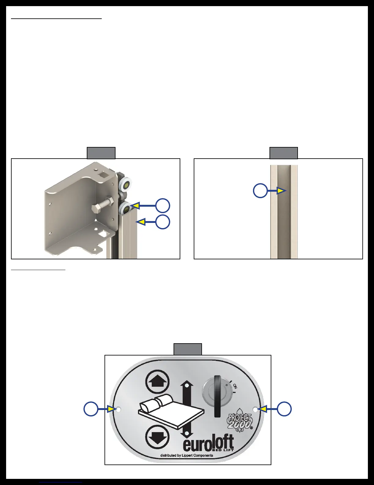
Euroloft Switch
NOTE: If installing on a unit with aluminum backing in the wall, use a minimum size of #10 x 1" self-drilling
screws. If installing on a unit with wood backing in the wall, use a minimum size of #10 x 1" wood
screws.
The Euroloft switch can be installed in the wall of the unit next to the bed frame or if installing padded rails
to the bed frame, in the padded rails.
1. Cut into the wall or the side panel of the bed an area 3" X 2" X 1" for the switch plate to be installed.
2. Install two #10 x 1/2" screws one screw on each side of the switch plate (Fig 19A).
Fig. 19
A A
 Loading...