Beta Draft Confidential
16 Proliphix Internet Managed Thermostat (IMT) Installation Guide
Part No. 600-03100-000, Rev. 4
Installing and Wiring the Thermostat
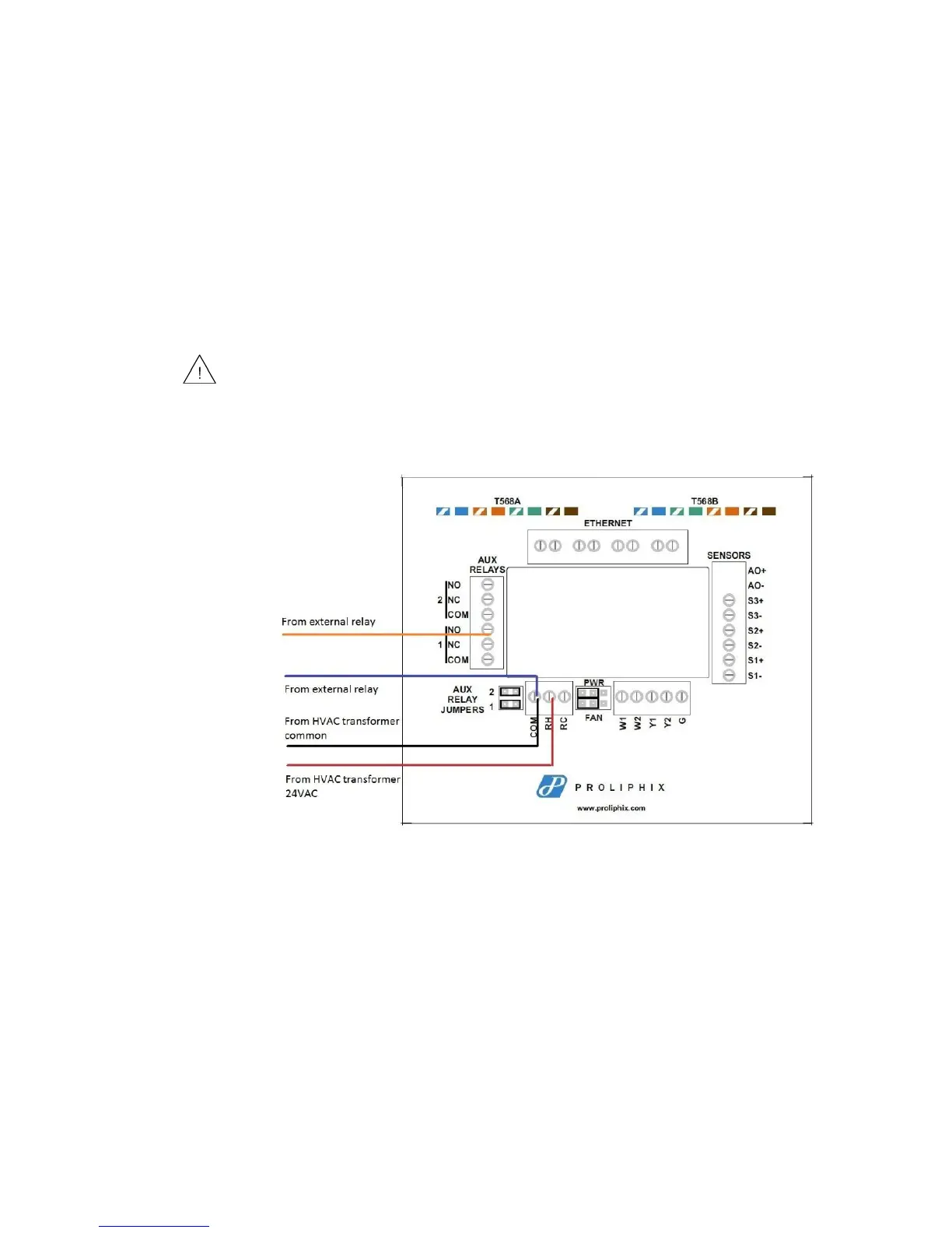
In this configuration, the installer uses the 24Vac power of the HVAC system
transformer to supply a 24Vac source back to the external relay. The red line in the
diagram represents the circuit path as it flows between the external relay and the aux
relay on the IMT550.
In this type of setup, the installer connects one wire of the external relay to the
Common (C or COM) side of the HVAC transformer. The other connection from the
external relay is connected to either the Normally Open (NO) or Normally Closed
(NC) terminal block on the IMT550 backplate. In most installations, the NO
connection is used so when the relay is not active, it stays in an open circuit state.
Figure 10 depicts backplate wiring.
Figure 10 Wiring Diagram of Relay Setup Using HVAC Transformer as Power
Source
Configuring Auxiliary Relay Jumpers
The Auxiliary Relays are powered from RC when the jumpers are installed. Figure 11
shows how to configure the Auxiliary Relay jumpers. Auxiliary Relay 1 and 2 can be
configured independently from each other.
The Aux Relay Jumpers must be on when using the HVAC transformer
power.source.